Detector Switches/ESE22
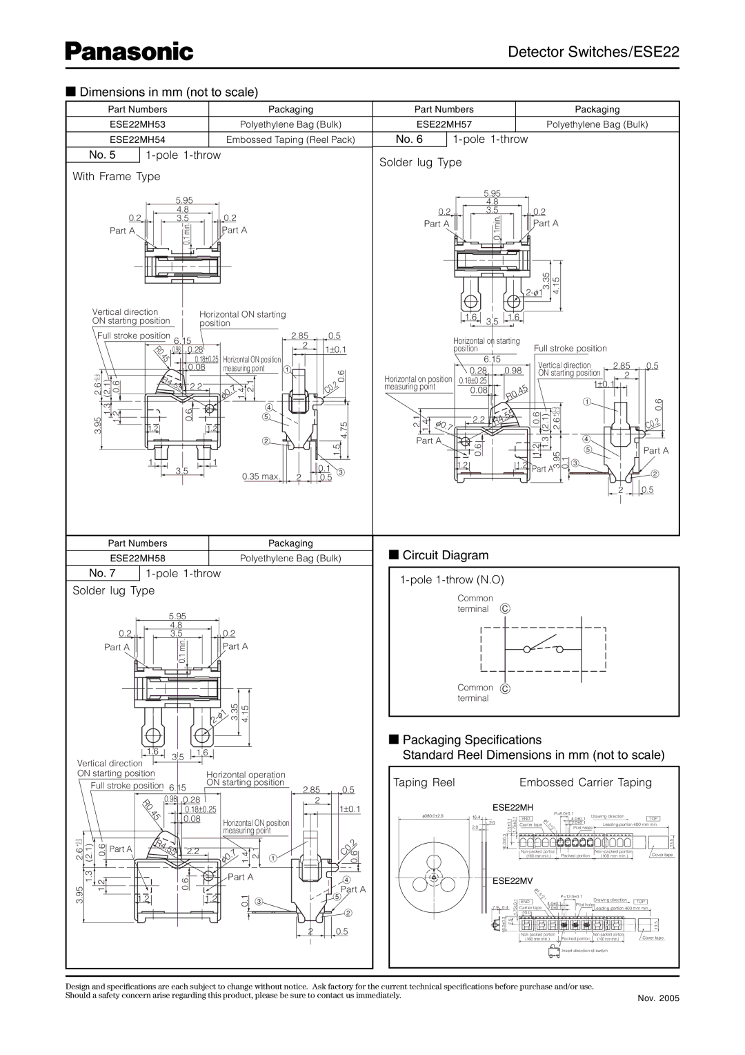
■Dimensions in mm (not to scale)
Part Numbers |
| Packaging | |
ESE22MH53 |
| Polyethylene Bag (Bulk) | |
ESE22MH54 |
| Embossed Taping (Reel Pack) | |
|
|
|
|
No. 5 |
|
| |
With Frame Type
| 5.95 |
|
0.2 | 4.8 | 0.2 |
3.5 | ||
Part A | min. | Part A |
| 0.1 |
|
Vertical direction |
|
|
| Horizontal ON starting |
|
|
ON starting position |
|
|
| position |
|
|
Full stroke position 6 |
| 5 |
| 2.85 | 0.5 | |
.1 |
| |||||
|
|
|
|
| 2 | 1±0.1 |
R0 | 0.98 0.28 | |||||
. |
| |||||
Part Numbers |
| Packaging | |
ESE22MH57 |
| Polyethylene Bag (Bulk) | |
|
|
|
|
No. 6 |
|
| |
|
|
|
|
Solder lug Type
| 5.95 |
|
|
|
| 4.8 |
|
|
|
0.2 | 3.5 |
| 0.2 |
|
Part A | 0.1min. |
| Part A | |
|
|
|
| |
|
|
| 3.35 | 4.15 |
|
|
|
| |
1.6 | 3.5 | 1.6 |
|
|
|
|
|
| |
Horizontal on starting | Full stroke position | |||
position |
|
| ||
|
|
| 45 | 0.18±0.25 Horizontal ON position |
|
| ||||
3 2 |
|
| R |
| 0.08 | measuring point | 1 | 0.6 | ||
|
| 4. |
|
|
|
|
| |||
+0. | (2.1) | 0.6 |
|
|
|
| 1.4 2.1 |
| .2 | |
| 55 | 2.2 |
| 7 |
| |||||
|
|
|
| |||||||
|
|
|
| . |
| C0 | ||||
|
|
| 0 |
| ||||||
|
|
| φ |
|
|
| ||||
| 1.3 | 1.2 |
|
| 0.6 |
|
| 4 |
|
|
3.95 |
|
|
|
| 5 |
| 4.75 | |||
1.2 |
| 1.2 |
|
|
| |||||
|
|
|
| 2 |
| |||||
|
|
|
|
|
|
|
|
| 1.5 | |
|
|
| 1 |
|
| 1 |
|
|
| |
|
|
| 3.5 |
|
|
| 0.1 | |||
|
|
|
|
|
|
|
| |||
|
|
|
|
|
| 0.35 max. | 2 | 0.5 3 | ||
|
|
|
|
|
|
|
| |||
Horizontal on position measuring point
2.1 | 1.4 | 7 | ||
|
|
| φ0. | |
|
|
| ||
|
|
|
|
|
Part A
6.15
0.280.98
0.18±0.25
0.08.45 R0
2.2 | .55 |
R4 | |
0.6 |
|
1.21.2
Vertical direction | 2.85 | 0.5 | ||||
ON starting position | 2 |
| ||||
|
|
|
| 1±0.1 |
| |
|
| +0.3 |
| 1 |
| 0.6 |
0.6 | (2.1) |
|
|
| ||
|
|
| .2 | |||
|
|
|
|
|
| C0 |
.2 | 1.3 |
|
| 4 |
|
|
|
| 5 |
| Part A | ||
1 |
| 3.95 | 0.1 |
| ||
| 3 |
|
| |||
Part A |
|
|
| 2 | ||
|
|
|
|
|
| |
|
|
|
|
| 2 | 0.5 |
Part Numbers |
| Packaging | |
|
|
|
|
ESE22MH58 |
| Polyethylene Bag (Bulk) | |
|
|
|
|
No. 7 |
| ||
Solder lug Type
| 5.95 |
|
|
|
|
| 4.8 |
|
|
|
|
0.2 | 3.5 |
| 0.2 |
| |
Part A | min. |
| Part A | ||
| 0.1 |
|
|
|
|
|
|
| 1 | 3.35 | 4.15 |
|
| φ |
|
| |
|
| - |
|
|
|
|
| 2 |
|
|
|
1.61.6
3.5![]()
![]()
Vertical direction |
|
|
|
|
|
|
|
|
|
| ||||
ON starting position |
|
| Horizontal operation |
|
|
| ||||||||
| Full stroke position | 6.15 | ON starting position | 2.85 | 0.5 | |||||||||
|
|
|
|
|
| |||||||||
|
|
|
| R0 | 0.98 | 0.28 |
|
|
|
|
| 2 | 1±0.1 | |
|
|
|
|
| 0.18±0.25 |
|
|
|
|
| ||||
|
|
|
| 4 |
|
|
|
|
|
| ||||
|
|
|
| . |
| 0.08 |
|
|
|
|
|
|
|
|
|
|
|
| 5 |
| Horizontal ON position |
|
|
| |||||
|
|
|
|
|
|
|
|
| ||||||
|
|
|
|
|
|
|
|
|
| |||||
(2.1) | 0.6 |
|
|
|
| measuring point |
|
| 0.6 | |||||
| R4. |
| φ |
| 1.4 | 2.1 | 1 |
|
| |||||
+0.3 |
|
| Part A |
| 55 | 2.2 |
|
|
|
|
|
| .2 | |
|
|
|
|
| 7 |
|
|
|
| C0 |
| |||
|
|
|
|
|
|
|
| . |
|
|
|
|
| |
3.95 |
|
|
|
|
|
| 0 |
|
|
|
| 5Part A | ||
1.3 | 1.2 |
| 1.2 |
| 0.6 | 1.2 |
| 0.1 | 3 |
|
| |||
|
|
|
|
|
|
|
| Part A |
|
| 4 | |||
|
|
|
|
|
|
|
|
|
|
|
|
| ||
|
|
|
|
|
|
|
|
|
|
|
|
| 2 | |
|
|
|
|
|
|
|
|
|
|
|
| 2 | 0.5 |
|
■Circuit Diagram
1-pole 1-throw (N.O)
Common terminal C
Common C terminal
■Packaging Specifications
Standard Reel Dimensions in mm (not to scale)
Taping Reel |
|
|
| Embossed Carrier Taping | ||||||
| ESE22MH | P=8.0±0.1 |
|
|
|
| ||||
φ380.0±2.0 | 16.4 | 0.17.5± 0.11.75± |
|
|
| Drawing direction |
| |||
END | φ | 4.0±0.1 | TOP | |||||||
| 2.0 |
|
|
| . | 2.0±0.1 |
|
| ||
|
|
|
| Carrier tape | 1 |
|
|
| Leading portion 400 mm min. | |
| 2.0 |
|
| 5+0 |
|
|
| |||
|
|
|
| 0 1 | Pilot holes |
| ||||
|
|
|
|
| . |
|
|
|
|
|
| 16.0±0.3 |
|
|
|
|
| 13.5 | |||
|
|
|
| Packed portion | Cover tape | |||||
|
|
|
| (160 mm min.) | (100 mm min.) | |||||
| ESE22MV |
|
|
|
|
|
| |||
|
|
|
| φ |
|
|
|
|
|
|
|
|
|
| 1 |
|
|
|
|
|
|
|
|
|
| . |
|
|
|
|
|
|
|
|
|
| 5 |
| P=12.0 | ± | 0.1 |
|
|
|
|
|
| 0. |
|
| ||||
|
|
|
|
| 1 |
|
|
| ||
|
|
|
| +0 |
|
|
|
|
| |
|
|
| 0.1 | END | 4.0±0.1 |
|
| Drawing direction | TOP | |
|
|
| Pilot holes | |||||||
| 7.9 0.4 | ± | Carrier tape | 2.0±0.1 |
| |||||
| 1.75 |
|
| Leading portion 400 mm min. | ||||||
| 16.0±0.3 |
| 10.0 |
|
|
|
|
|
| |
|
| 7.5 |
|
|
| 13.5 | ||||
|
|
|
| Packed portion | Cover tape | |||||
|
|
|
| (160 mm min.) | (100 mm min.) | |||||
Insert direction of switch
Design and specifications are each subject to change without notice. Ask factory for the current technical specifications before purchase and/or use. |
|
Should a safety concern arise regarding this product, please be sure to contact us immediately. | Nov. 2005 |
|