SLIM POWER RELAY |
|
WITH HIGH INRUSH | |
CURRENT CAPABILITY | |
|
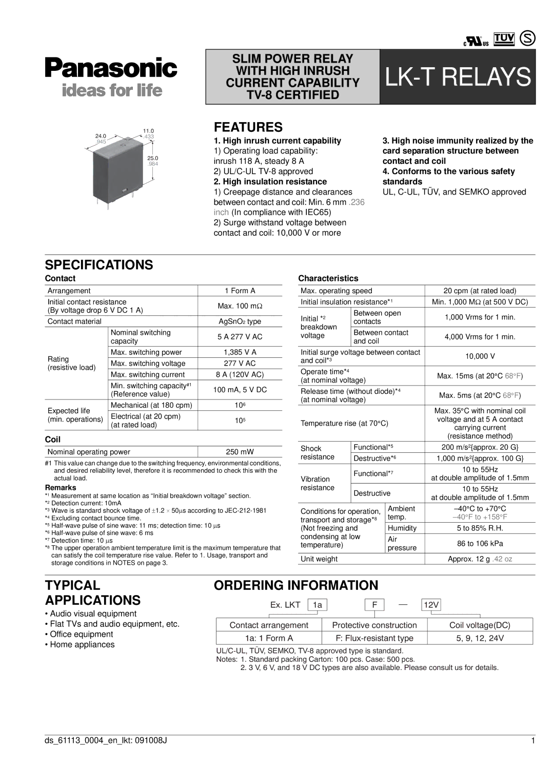
24.0 | 11.0 |
.433 |
.945
25.0
.984
FEATURES
1.High inrush current capability
1) Operating load capability: inrush 118 A, steady 8 A
2)
2.High insulation resistance
1)Creepage distance and clearances between contact and coil: Min. 6 mm .236 inch (In compliance with IEC65)
2)Surge withstand voltage between contact and coil: 10,000 V or more
3.High noise immunity realized by the card separation structure between contact and coil
4.Conforms to the various safety standards
UL,
SPECIFICATIONS
Contact
Arrangement |
| 1 Form A | |
Initial contact resistance | Max. 100 mΩ | ||
(By voltage drop 6 V DC 1 A) | |||
| |||
Contact material |
| AgSnO2 type | |
| Nominal switching | 5 A 277 V AC | |
| capacity | ||
|
| ||
Rating | Max. switching power | 1,385 V A | |
Max. switching voltage | 277 V AC | ||
(resistive load) | |||
Max. switching current | 8 A (120V AC) | ||
| |||
| Min. switching capacity#1 | 100 mA, 5 V DC | |
| (Reference value) | ||
|
| ||
Expected life | Mechanical (at 180 cpm) | 106 | |
Electrical (at 20 cpm) |
| ||
(min. operations) | 105 | ||
| (at rated load) |
| |
Coil
Nominal operating power | 250 mW |
#1 This value can change due to the switching frequency, environmental conditions, and desired reliability level, therefore it is recommended to check this with the actual load.
Remarks
*1 Measurement at same location as “Initial breakdown voltage” section. *2 Detection current: 10mA
*3 Wave is standard shock voltage of ±1.2 ⋅ 50μs according to
*5
*6
*7 Detection time: 10 μs
*8 The upper operation ambient temperature limit is the maximum temperature that can satisfy the coil temperature rise value. Refer to 1. Usage, transport and storage conditions in NOTES on page 3.
Characteristics
Max. operating speed |
| 20 cpm (at rated load) | ||
Initial insulation resistance*1 | Min. 1,000 MΩ (at 500 V DC) | |||
Initial *2 | Between open | 1,000 Vrms for 1 min. | ||
contacts |
| |||
breakdown |
|
| ||
Between contact |
| |||
voltage | 4,000 Vrms for 1 min. | |||
and coil |
| |||
|
|
| ||
Initial surge voltage between contact | 10,000 V | |||
and coil*3 |
|
| ||
|
|
| ||
Operate time*4 |
|
| Max. 15ms (at 20°C 68°F) | |
(at nominal voltage) |
| |||
|
| |||
Release time (without diode)*4 | Max. 5ms (at 20°C 68°F) | |||
(at nominal voltage) |
| |||
|
| |||
|
|
| Max. 35°C with nominal coil | |
Temperature rise (at 70°C) | voltage and at 5 A contact | |||
carrying current | ||||
|
|
| ||
|
|
| (resistance method) | |
Shock | Functional*5 | 200 m/s2{approx. 20 G} | ||
resistance | Destructive*6 | 1,000 m/s2{approx. 100 G} | ||
| Functional*7 | 10 to 55Hz | ||
Vibration | at double amplitude of 1.5mm | |||
|
| |||
resistance | Destructive | 10 to 55Hz | ||
| at double amplitude of 1.5mm | |||
|
|
| ||
Conditions for operation, | Ambient | |||
transport and storage*8 | temp. |
| ||
(Not freezing and | Humidity | 5 to 85% R.H. | ||
condensing at low |
|
| ||
Air | 86 to 106 kPa | |||
temperature) |
| |||
| pressure | |||
|
|
| ||
Unit weight |
|
| Approx. 12 g .42 oz | |
TYPICAL
APPLICATIONS
•Audio visual equipment
•Flat TVs and audio equipment, etc.
•Office equipment
•Home appliances
ORDERING INFORMATION
|
| Ex. LKT | 1a |
| F |
|
|
| 12V |
| |||||||
|
|
|
|
|
|
|
|
| |||||||||
|
|
|
|
|
|
|
|
|
|
|
|
|
|
|
| ||
Contact arrangement |
| Protective construction |
|
|
| Coil voltage(DC) | |||||||||||
|
|
|
|
|
|
|
|
|
| ||||||||
1a: 1 Form A |
| F: |
|
|
| 5, 9, 12, 24V | |||||||||||
|
|
|
|
|
|
|
|
|
|
|
|
|
|
|
|
|
|
2. 3 V, 6 V, and 18 V DC types are also available. Please consult us for details.
ds_61113_0004_en_lkt: 091008J | 1 |