Stationary 2D Code Reader PD50
System Configuration
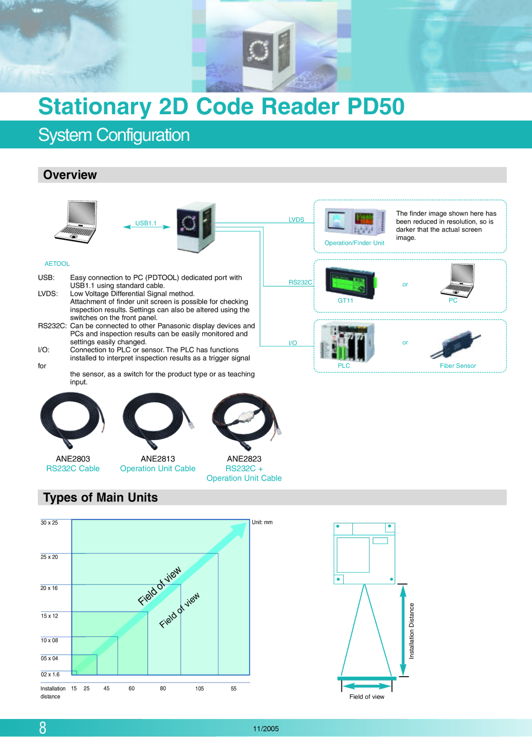
Overview
USB1.1
LVDS
The finder image shown here has been reduced in resolution, so is darker that the actual screen image.
AETOOL |
|
USB: | Easy connection to PC (PDTOOL) dedicated port with |
| USB1.1 using standard cable. |
LVDS: | Low Voltage Differential Signal method. |
| Attachment of finder unit screen is possible for checking |
| inspection results. Settings can also be altered using the |
| switches on the front panel. |
RS232C: Can be connected to other Panasonic display devices and
| PCs and inspection results can be easily monitored and |
| settings easily changed. |
I/O: | Connection to PLC or sensor. The PLC has functions |
| installed to interpret inspection results as a trigger signal |
Operation/Finder Unit
RS232C
GT11
I/O
or
PC
or
for | PLC | Fiber Sensor |
| the sensor, as a switch for the product type or as teaching |
|
| input. |
|
ANE2803 | ANE2813 | ANE2823 |
RS232C Cable | Operation Unit Cable | RS232C + |
Operation Unit Cable
Types of Main Units
30 x 25
25 x 20
20 x 16
15 x 12
Field
of | view |
| |
|
|
| |
|
| of | view |
Field |
| ||
|
| ||
Unit: mm
Distance
10 x 08
05 x 04
02 x 1.6
Installation | 15 | 25 | 45 | 60 | 80 | 105 | 55 |
distance |
|
|
|
|
|
|
|
Field of view
Installation
8 | 11/2005 |