RM-1100 specifications
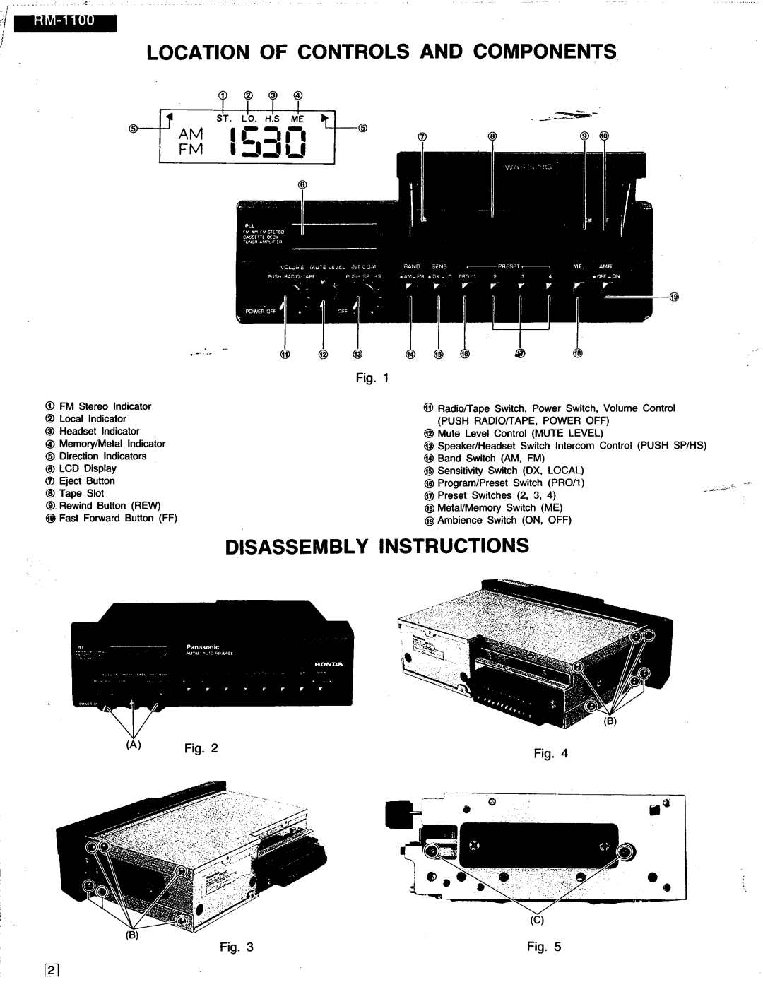
The Panasonic RM-1100 is a versatile and innovative piece of technology that has gained attention for its range of features and capabilities. Designed for both professional and consumer use, this device stands out in the market due to its high-quality performance and user-friendly interface.One of the main features of the RM-1100 is its advanced audio processing technology. This device is equipped with state-of-the-art sound enhancement algorithms that ensure clear and crisp audio playback. Whether used for presentations, music playback, or multimedia projects, the audio quality remains consistent, making it suitable for various uses.
Another notable characteristic of the RM-1100 is its impressive connectivity options. The device supports multiple input and output formats, allowing users to connect it to a wide range of devices, including computers, speakers, and other audio equipment. This versatility is essential for users who require seamless integration into different setups.
The design of the RM-1100 emphasizes ease of use. With an intuitive interface and straightforward controls, users can quickly navigate through settings and functionalities without extensive training. The compact and portable design also makes it easy to transport, which is especially beneficial for professionals who need to work in different environments.
In terms of build quality, Panasonic is known for its durability, and the RM-1100 is no exception. Constructed from high-quality materials, it is built to withstand the rigors of daily use. This reliability ensures that users can depend on the device for both long-term projects and quick tasks.
The RM-1100 also incorporates energy-efficient technologies. The device is designed to consume less power while maintaining optimal performance. This focus on energy efficiency is not only environmentally friendly but also beneficial for users looking to reduce their energy costs.
Additionally, the RM-1100 is compatible with various software applications, enhancing its functionality further. Users can leverage additional features through software integration, making it a dynamic tool for creative professionals and casual users alike.
Overall, the Panasonic RM-1100 is a well-rounded device that offers a blend of quality, performance, and convenience. Its advanced audio technology, excellent connectivity, user-friendly design, and durability make it an attractive option for anyone in need of a reliable audio solution.

