Technical Information (Continued)
DATA/MTI (RJ11) terminal connection
A standard 6 pin
External TA
Multiple Television Interface(MTI)
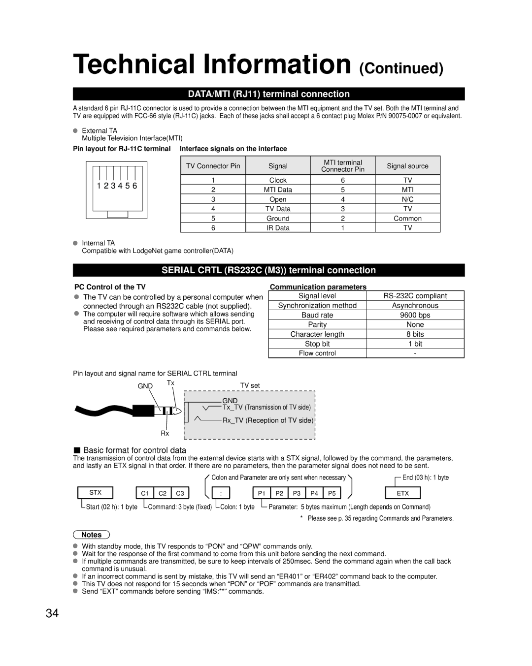
Pin layout for |
|
| ||||||||||||
|
|
|
|
|
|
|
|
|
|
|
|
|
|
|
|
|
|
|
|
|
|
|
|
|
| TV Connector Pin | Signal | MTI terminal | Signal source |
|
|
|
|
|
|
|
|
|
|
| Connector Pin | |||
|
|
|
|
|
|
|
|
|
|
|
|
|
| |
|
|
|
|
|
|
|
|
|
|
| 1 | Clock | 6 | TV |
|
| 1 2 3 4 5 6 |
| |||||||||||
|
|
|
| 2 | MTI Data | 5 | MTI | |||||||
|
|
|
|
|
|
|
|
|
|
| ||||
|
|
|
|
|
|
|
|
|
|
| 3 | Open | 4 | N/C |
|
|
|
|
|
|
|
|
|
|
| 4 | TV Data | 3 | TV |
|
|
|
|
|
|
|
|
|
|
| 5 | Ground | 2 | Common |
|
|
|
|
|
|
|
|
|
| |||||
|
|
|
|
|
|
|
|
|
| |||||
|
|
|
|
|
|
|
|
|
|
| 6 | IR Data | 1 | TV |
Internal TA
Compatible with LodgeNet game controller(DATA)
SERIAL CRTL (RS232C (M3)) terminal connection
PC Control of the TV
The TV can be controlled by a personal computer when connected through an RS232C cable (not supplied).
The computer will require software which allows sending and receiving of control data through its SERIAL port. Please see required parameters and commands below.
Pin layout and signal name for SERIAL CTRL terminal
Communication parameters
Signal level | |
Synchronization method | Asynchronous |
Baud rate | 9600 bps |
Parity | None |
Character length | 8 bits |
Stop bit | 1 bit |
Flow control | - |
GND Tx
Rx
TV set
GND
Tx_TV (Transmission of TV side)
Rx_TV (Reception of TV side)
■Basic format for control data
The transmission of control data from the external device starts with a STX signal, followed by the command, the parameters, and lastly an ETX signal in that order. If there are no parameters, then the parameter signal does not need to be sent.
|
|
|
|
|
|
|
|
|
| Colon and Parameter are only sent when necessary |
|
| End (03 h): 1 byte | ||||||||||||||
|
|
|
|
|
|
|
|
|
|
|
| ||||||||||||||||
|
|
|
|
|
|
|
|
|
|
|
|
|
|
|
|
|
|
|
|
|
|
|
|
|
|
|
|
|
| STX |
|
| C1 | C2 | C3 |
| : |
|
| P1 | P2 | P3 | P4 | P5 |
|
| ETX |
| |||||||
|
| Start (02 h): 1 byte |
|
| Command: 3 byte (fixed) |
|
| Colon: 1 byte |
|
| Parameter: 5 bytes maximum (Length depends on Command) | ||||||||||||||||
|
|
|
|
|
|
| |||||||||||||||||||||
* Please see p. 35 regarding Commands and Parameters.
Notes
With standby mode, this TV responds to “PON” and “QPW” commands only.
Wait for the response of the first command to come from this unit before sending the next command.
If multiple commands are transmitted, be sure to keep intervals of 250msec. Send the command again when the call back command is unusual.
If an incorrect command is sent by mistake, this TV will send an “ER401” or “ER402” command back to the computer. This TV does not respond for 15 seconds when “PON” or “POF” commands are transmitted.
Send “EXT” commands before sending “IMS:**” commands.
34