868 specifications
The ParaBody 868 is an advanced piece of fitness equipment designed to elevate the workout experience for fitness enthusiasts and athletes alike. By combining innovation with functionality, the ParaBody 868 serves to meet the diverse needs of users seeking comprehensive strength training solutions.One of the standout features of the ParaBody 868 is its multi-station design, which allows users to perform a wide range of exercises in one compact unit. This versatility makes it suitable for various workout routines, targeting major muscle groups, and is ideal for both beginners and seasoned athletes. The machine is equipped with numerous adjustable components that can be tailored to individual fitness levels, ensuring a personalized workout experience.
The structure of the ParaBody 868 is engineered for durability and stability. It features a robust steel frame that can withstand rigorous training sessions and heavy weights. Additionally, the premium quality materials used in its construction ensure longevity, minimizing wear and tear over time. The machine’s design prioritizes user safety, incorporating ergonomic features that facilitate proper form during exercises to help prevent injuries.
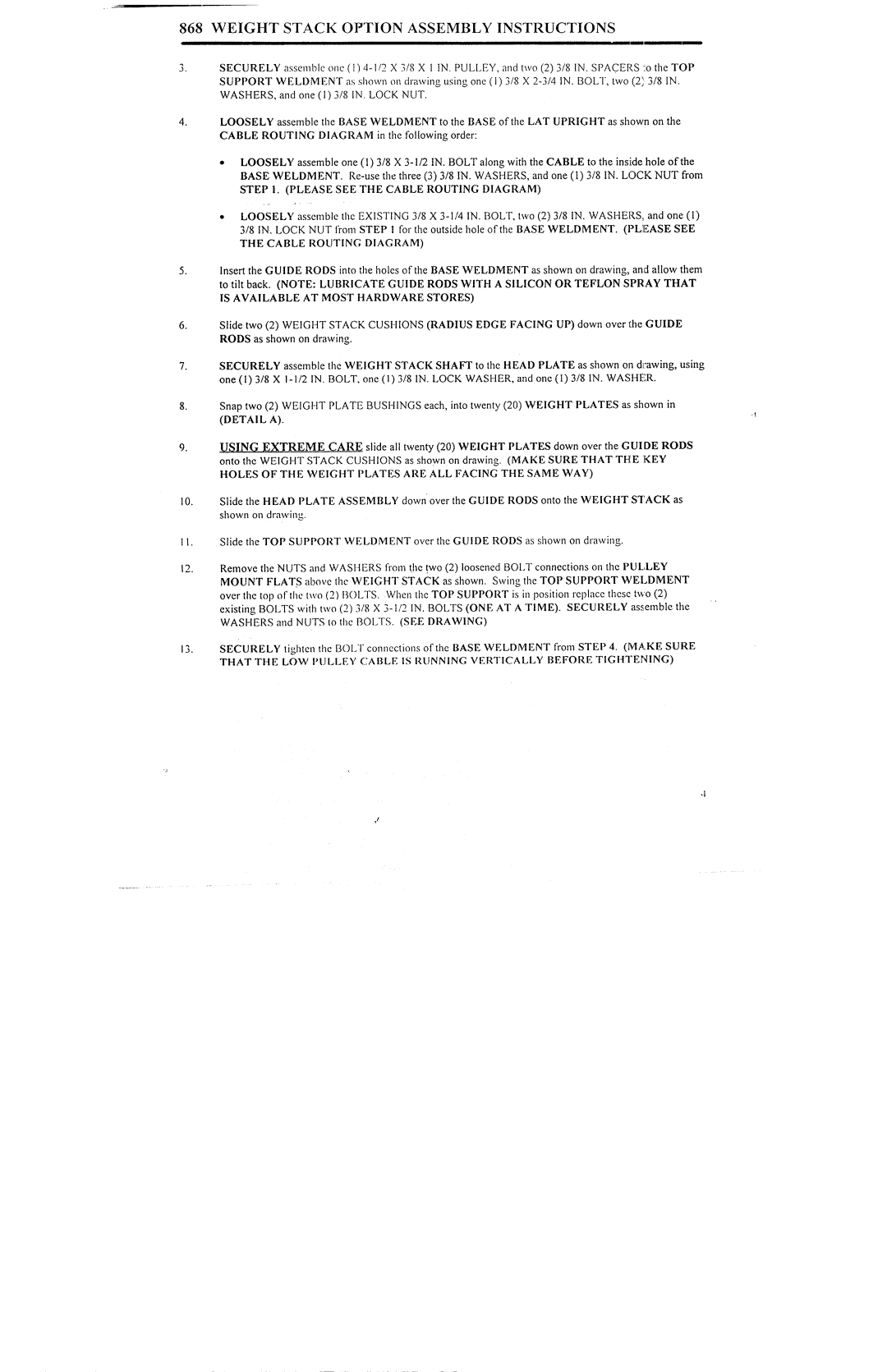
Technologically, the ParaBody 868 is equipped with a weight stack system that allows for smooth and controlled adjustments. This system ensures seamless transitions between exercises, allowing users to efficiently switch from one movement to another without interruption. The weight stack is designed to provide a sufficient range of resistance, catering to a variety of strength training needs, from rehabilitation to muscle building.
Another notable characteristic of the ParaBody 868 is its compact footprint. This makes it an excellent choice for home gyms or smaller fitness spaces where maximizing available area is crucial. Despite its size, the machine does not compromise on functionality, as it offers a plethora of workout options, including cable exercises, lat pull-downs, leg extensions, and more.
In summary, the ParaBody 868 is a versatile and durable strength training system that combines a multi-station design with advanced features and user-friendly technologies. Whether for personal fitness goals or professional training, this machine stands out as an effective solution for optimizing one’s workout routine while ensuring safety and structural integrity. Ultimately, the ParaBody 868 is an investment in health and fitness, promising to deliver results that redefine strength training.

