| |
PRINTED IN CANADA 07/2004 | |
|
Instructions
780 Industriel Blvd., | CANADA | |
Tel.: (450) | Fax: (450) | |
| www.paradox.ca |
|
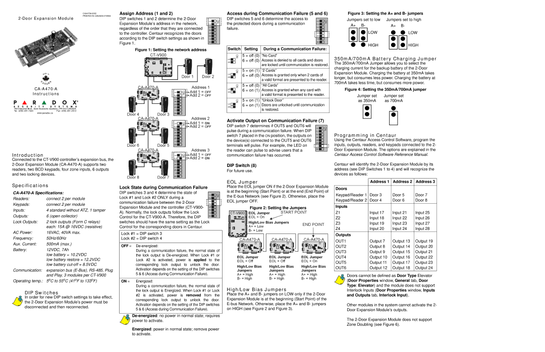
Assign Address (1 and 2)
DIP switches 1 and 2 determine the
Figure 1: Setting the network address
Access during Communication Failure (5 and 6)
DIP switches 5 and 6 determine the access to the protected doors during a communication failure.
Switch | Setting | During a Communication Failure: | |
|
|
|
|
| 5 | = off (0) | “No Card” |
| 6 | = off (0) | Access is denied to all cards and doors |
|
|
| are locked until communication is restored. |
| 5 | = on (1) | “2 Cards” |
| 6 | = off (0) | Access is granted only when 2 cards of |
|
|
| a valid format are presented to the reader. |
| 5 | = off (0) | “All Cards” |
| 6 | = on (1) | Access is granted when any card with |
|
|
| a valid format is presented to the reader. |
|
|
|
|
| 5 | = on (1) | “Unlock Door” |
| 6 | = on (1) | Doors are unlocked until communication |
|
|
| is restored. |
Figure 3: Setting the A+ and B- jumpers
Jumpers set to low | Jumpers set to high | ||||||||
| A+ B- |
| A+ B- | ||||||
|
|
|
| LOW |
|
|
|
| LOW |
|
|
|
| HIGH |
|
|
|
| HIGH |
|
|
|
|
|
|
|
| ||
|
|
|
|
|
|
|
|
|
|
350mA/700mA Battery Charging Jumper
The 350mA/700mA Jumper allows you to select the charging current for the backup battery of the
Figure 4: Setting the 350mA/700mA jumper
Jumper set | Jumper set |
as 350mA | as 700mA |
Introduction
Connected to the
Activate Output on Communication Failure (7)
DIP switch 7 determines if OUT5 and OUT6 will pulse during a communication failure. When DIP switch 7 placed in the ON position, the outputs on the device(s) connected to the OUT5 and OUT6 terminals will pulse. For example, the LED on the reader can pulse to advise users that a communication failure has occurred.
DIP Switch (8)
For future use.
Programming in Centaur
Using the Centaur Access Control Software, program the inputs, outputs, readers, and keypads connected to the 2- Door Expansion Module. The options are explained in the Centaur Access Control Software Reference Manual.
Centaur will identify the
Specifications
CA-A470-A Specifications:
Readers: | connect 2 per module |
Keypads: | connect 2 per module |
Inputs: | 4 standard without ATZ, 1 tamper |
Outputs: | 6 (open collector) |
Lock Outputs: | 2 lock outputs (Form C relays) |
| each: 15A @ 16VDC (resistive) |
AC Power: | 16VAC, 40VA max. |
Frequency: | 50Hz/60Hz |
Aux. Current: | 500mA (max.) |
Battery: | 12VDC, 7Ah |
| low battery = 10.2VDC |
| low battery restore = 12.2VDC |
| low battery |
Communication: expansion bus
Operating temp.: 5oC to 55oC (41oF to 133oF)
DIP Switches
In order for new DIP switch settings to take effect, the
Lock State during Communication Failure
DIP switches 3 and 4 determine the state of Lock #1 and Lock #2 ONLY during a communication failure between the
Lock #1 = DIP switch 3
Lock #2 = DIP switch 4
OFF = De-energized:
During a communication failure, the normal state of the lock output is
ON = Energized:
During a communication failure, the normal state of the lock output is Energized. When Lock #1 or Lock #2 is activated, power is removed from the corresponding lock output to unlock the door. Activation depends on the setting of the DIP switches 5 & 6 (Access during Communication Failure).
Energized: power in normal state; remove power to activate.
EOL Jumper
Place the EOL jumper ON if the
Figure 2: Setting the Jumpers
High/Low Bias Jumpers
Place the A+ and B- jumpers on LOW only if the
| Address 1 | Address 2 | Address 3 |
|
|
|
|
Doors |
|
|
|
Keypad/Reader 1 | Door 3 | Door 5 | Door 7 |
Keypad/Reader 2 | Door 4 | Door 6 | Door 8 |
Inputs |
|
|
|
Z1 | Input 17 | Input 21 | Input 25 |
Z2 | Input 18 | Input 22 | Input 26 |
Z3 | Input 19 | Input 23 | Input 27 |
Z4 | Input 20 | Input 24 | Input 28 |
Outputs |
|
|
|
OUT1 | Output 7 | Output 13 | Output 19 |
OUT2 | Output 8 | Output 14 | Output 20 |
OUT3 | Output 9 | Output 15 | Output 21 |
OUT4 | Output 10 | Output 16 | Output 22 |
OUT5 | Output 11 | Output 17 | Output 23 |
OUT6 | Output 12 | Output 18 | Output 24 |
Doors cannot be defined as Door Type Elevator (Door Properties window, General tab, Door Type: Elevator) and the module does not support Interlock Inputs (Door Properties window, Inputs and Outputs tab, Interlock Input).
Other modules in the system cannot activate the 2- Door Expansion Module’s outputs.
The