Wiring the PEM
HANDLING PRECAUTIONS FOR
!STATIC-SENSITIVE DEVICES
This product is designed to protect sensitive components from damage due to electrostatic discharge (ESD) during normal operation. When performing installation procedures, however, take proper static control precautions to prevent damage to equipment. If you are not sure of the proper static control precautions, contact your nearest sales or service representative.
Each PEM is equipped with an internal 35 amp (Model
The PEMs require 8 AWG wire for their power connections. If stranded wire is used, do not
Although power may be connected to the front of the PEMs, it is recommended that these connections be made at the rear of the chassis. Either way will work, but all power inputs must be made either to the front or to the rear of the chassis, not both.
NOTE:
Both PWR A and PWR B must be powered, else the management card alarm will be activated.
CLOCK | SERIAL | AC |
|
|
|
|
|
|
|
|
|
|
A | MCC | ALARM | 2 | 4 | 6 | 8 | LANA/WAN S1L0OT |
|
|
|
| |
|
|
| 12 | 14 | 16 | 18 | ||||||
|
|
|
|
|
|
|
|
| ||||
CLOBCK | SSEMRCIAML ALARM | 1 | 3 | 5 | 7 | 9 | B | 11 | 13 | 15 | 17 | |
|
|
|
|
|
|
|
| |||||
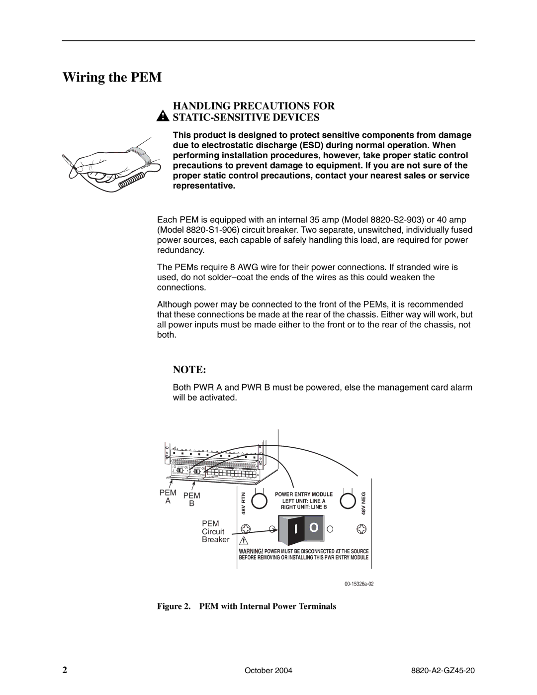
APEM
BPEM
PEM
Circuit
Breaker
RTN | POWER ENTRY MODULE |
LEFT UNIT: LINE A | |
48V | RIGHT UNIT: LINE B |
| |
| O |
WARNING! POWER MUST BE DISCONNECTED | |
BEFORE REMOVING OR INSTALLING THIS PWR | |
NEG48V
AT THE SOURCE ENTRY MODULE
Figure 2. PEM with Internal Power Terminals
2 | October 2004 |