275 V.2 specifications
The Parasound 275 V.2 is a powerful and versatile amplifier that stands out in the crowded landscape of audio equipment. Known for its robust construction and high-quality performance, it has become a favorite among audiophiles and home theater enthusiasts alike.At the heart of the 275 V.2 is its impressive power output. Delivering 2 x 60 watts into 8 ohms and 2 x 90 watts into 4 ohms, this amplifier can easily drive a variety of speakers efficiently. This output is achieved with a toroidal transformer and high-capacity filter capacitance, ensuring a clean and dynamic sound. The amplifier's ability to provide high current allows it to maintain performance under demanding conditions, making it a reliable choice for both music and movie playback.
One of the standout features of the Parasound 275 V.2 is its use of high-quality components. The amplifier employs discrete, low-noise, high-speed transistors for an ultra-linear frequency response, resulting in low distortion across all frequencies. Additionally, it features a full complement of protection circuitry that shields the amplifier and connected speakers from potential damage, which is a crucial aspect of long-term reliability.
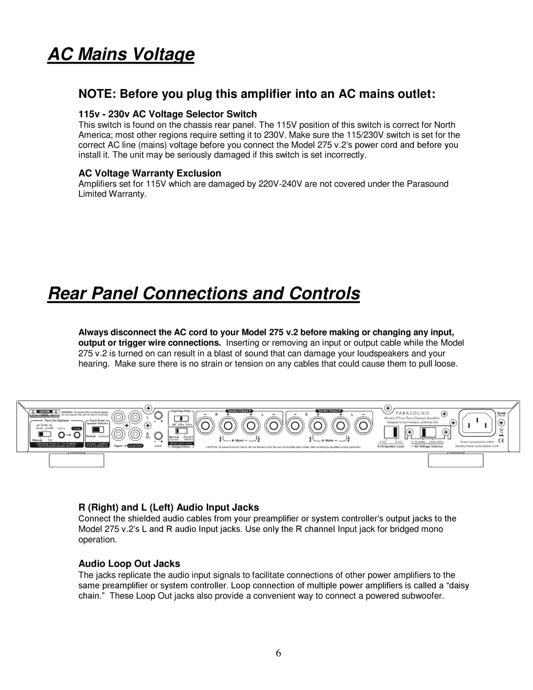
The design of the 275 V.2 also places a strong emphasis on versatility. It includes both unbalanced RCA inputs and balanced XLR inputs, allowing it to seamlessly integrate into a variety of audio systems. This flexibility is particularly beneficial for users with high-end source components that utilize balanced outputs.
User-friendly features like a 12V trigger input and output enable easy integration into automated systems, while the inclusion of a remote trigger output means the amplifier can work in conjunction with other powered devices. Furthermore, the amplifier has a front-panel power switch, which can be beneficial for quick access.
Aesthetically, the Parasound 275 V.2 is designed with a modern look, featuring a sleek chassis that is both durable and stylish. It also sports an elegant, minimalist front panel, which reflects the brand's commitment to quality.
In summary, the Parasound 275 V.2 is a high-performance amplifier that combines impressive power, superior build quality, and versatile connectivity options. Its innovative technologies and thoughtful engineering make it a top contender for anyone looking to elevate their audio experience, whether in a home theater or a dedicated listening room. With its balance of reliability and performance, the 275 V.2 is a commendable choice for discerning audio enthusiasts.

