
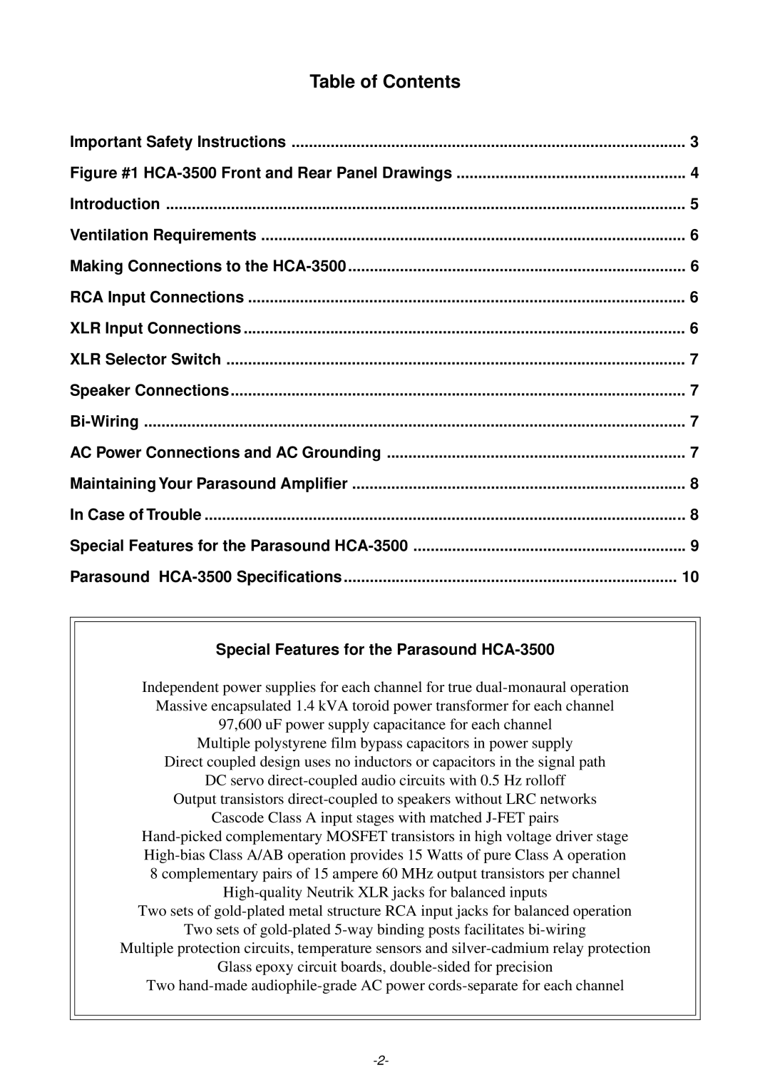
HCA-3500 specifications
The Parasound HCA-3500 is a high-performance power amplifier renowned for its robust design and exceptional audio quality. This model is part of Parasound's Classic series, aimed at audiophiles seeking both power and fidelity in their audio systems. With a solid build and advanced technologies, the HCA-3500 continues to garner attention for its performance capabilities.One of the main features of the HCA-3500 is its powerful output, delivering 350 watts per channel into 8 ohms, and an impressive 700 watts per channel into 4 ohms. This ensures that the amplifier can drive a wide range of speakers with ease, particularly those requiring higher power levels to achieve optimal performance. The high current abilities of the HCA-3500 provide agility in dynamic musical passages, making it a favorite among professionals and enthusiasts alike.
The HCA-3500 employs a fully discrete, Class A/AB output stage. This design minimizes crossover distortion, allowing for a clean, transparent sound signature that captures the nuances of the original recording. The amplifier features a tight feedback loop that enhances stability while maintaining an excellent signal-to-noise ratio, contributing to its pristine audio reproduction.
One of the standout technologies in the HCA-3500 is its use of the proprietary Halo technology, which incorporates advanced circuit design and high-quality components. This includes gold-plated connectors and high-grade capacitors that enhance signal integrity and longevity. Moreover, the parasitic capacitance in the circuitry is minimized to further improve signal clarity.
In terms of build quality, the HCA-3500 is impressively robust, housed in a sturdy chassis that reduces vibration and interference. The amplifier’s layout is designed for efficient heat dissipation, featuring large heatsinks that help maintain optimal operating temperatures even under demanding conditions.
User-friendly features are also a highlight, such as the ability to bridge the amplifier for mono operation, enhancing its versatility in various setups. Additionally, the HCA-3500 includes a 12V trigger input, allowing for seamless integration with home theater systems and automation setups.
In summary, the Parasound HCA-3500 is an exemplary power amplifier that combines power, fidelity, and advanced technology in one package. Its capabilities make it suitable for both high-end audio systems and professional applications, ensuring that listeners enjoy a deeply immersive audio experience. With its commitment to audio excellence, the HCA-3500 continues to be a respected option for those who seek quality in amplifier performance.