4.0 INSTALLATION
The Model 1060 is easy to install. After configuring the DIP switches and DCE/DTE switches, connect the two twisted pairs using one of two methods: terminal blocks or
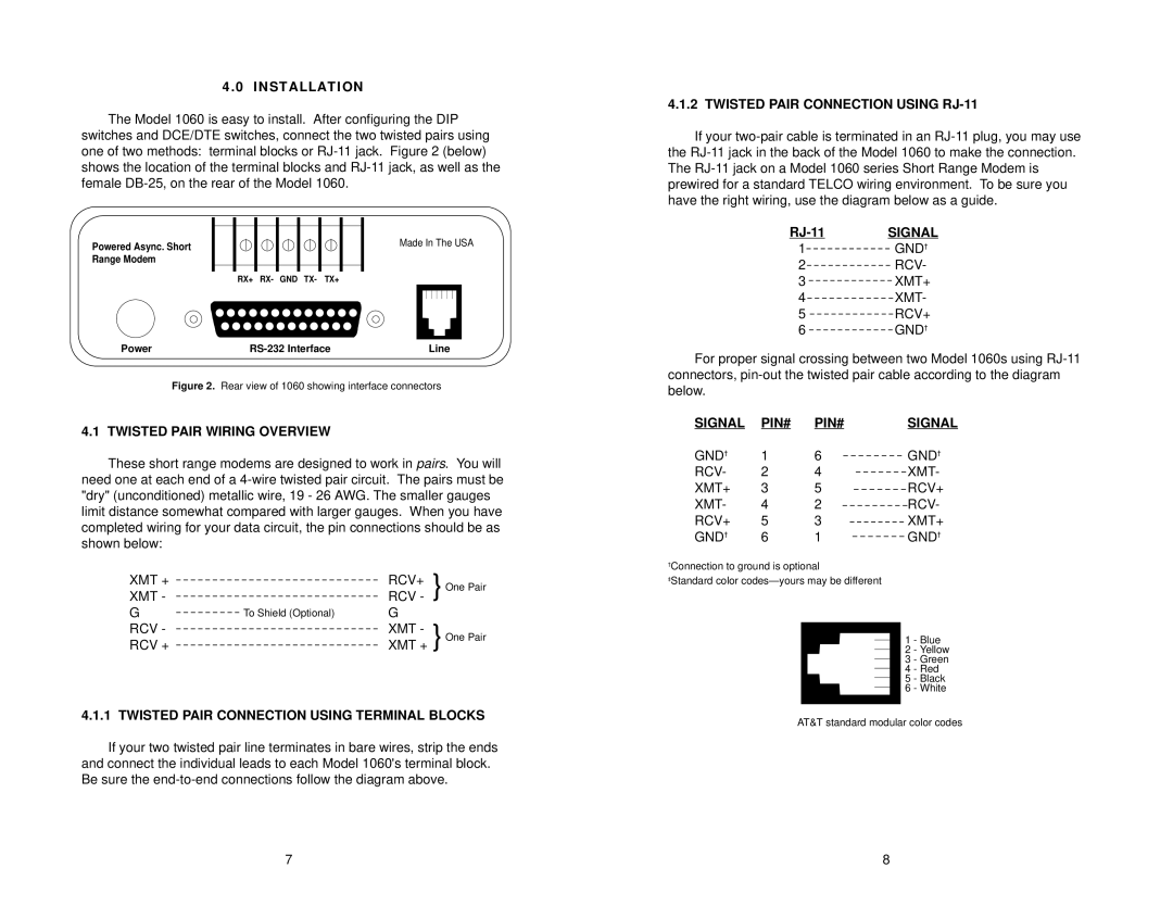
Powered Async. Short | Made In The USA |
| |
Range Modem |
|
| RX+ RX- GND TX- TX+ |
Power | Line |
Figure 2. Rear view of 1060 showing interface connectors
4.1 TWISTED PAIR WIRING OVERVIEW
These short range modems are designed to work in pairs. You will need one at each end of a
XMT + |
| RCV+ | } One Pair |
XMT - |
| RCV - | |
G | To Shield (Optional) | G |
|
RCV - |
| XMT - |
|
RCV + |
| XMT + } One Pair | |
4.1.1 TWISTED PAIR CONNECTION USING TERMINAL BLOCKS
If your two twisted pair line terminates in bare wires, strip the ends and connect the individual leads to each Model 1060's terminal block. Be sure the
4.1.2 TWISTED PAIR CONNECTION USING RJ-11
If your
RJ-11 SIGNAL
1GND†
2RCV-
3XMT+
4XMT-
5RCV+
6GND†
For proper signal crossing between two Model 1060s using
SIGNAL | PIN# | PIN# | SIGNAL |
GND† | 1 | 6 | GND† |
RCV- | 2 | 4 | XMT- |
XMT+ | 3 | 5 | RCV+ |
XMT- | 4 | 2 | RCV- |
RCV+ | 5 | 3 | XMT+ |
GND† | 6 | 1 | GND† |
†Connection to ground is optional
‡Standard color
1 - Blue
2 - Yellow
3 - Green
4 - Red
5 - Black
6 - White
AT&T standard modular color codes
7 | 8 |