147001UA
CHAPTER 2 - SETUP AND INSTALLATION
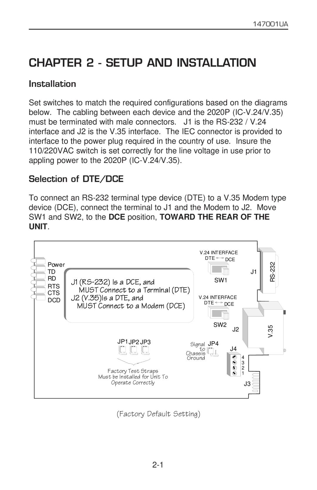
Installation
Set switches to match the required configurations based on the diagrams below. The cabling between each device and the 2020P
Selection of DTE/DCE
To connect an
![]()
![]() Power
Power
![]()
![]() TD
TD
![]() RD
RD
![]()
![]() RTS
RTS
![]()
![]()
![]() CTS
CTS ![]()
![]() DCD
DCD
J1
MUST Connect to a Terminal (DTE) J2 (V.35)Is a DTE, and
MUST Connect to a Modem (DCE)
V.24 INTERFACE
DTE ![]() DCE
DCE
J1
SW1
V.24 INTERFACE
DTE ![]() DCE
DCE
SW2 |
J2
V.35
JP1JP2 JP3 | Signal | JP4 |
| to | J4 |
| Chassis | 4 |
| Ground | |
|
| 3 |
Factory Test Straps |
| 2 |
| 1 | |
Must be Installed for Unit To |
| J3 |
Operate Correctly |
|
(Factory Default Setting)