Patton electronic 2025 user manual Led Status Monitors, LED Codes

Models: 2025

1 7
Download 7 pages 2.2 Kb
Page 5
Image 5
5.1 LED STATUS MONITORS

4.0 INSTALLATION

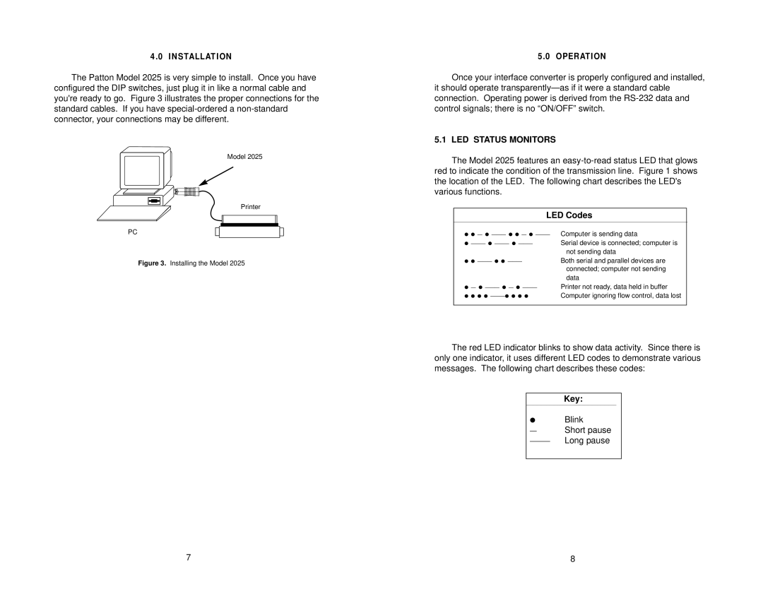
The Patton Model 2025 is very simple to install. Once you have configured the DIP switches, just plug it in like a normal cable and you're ready to go. Figure 3 illustrates the proper connections for the standard cables. If you have special-ordered a non-standard connector, your connections may be different.

Model 2025

Printer

PC

Figure 3. Installing the Model 2025

5.0 OPERATION

Once your interface converter is properly configured and installed, it should operate transparently—as if it were a standard cable connection. Operating power is derived from the RS-232 data and control signals; there is no “ON/OFF” switch.

5.1 LED STATUS MONITORS

The Model 2025 features an easy-to-read status LED that glows red to indicate the condition of the transmission line. Figure 1 shows the location of the LED. The following chart describes the LED's various functions.

LED Codes

● ● — ● ——— ● ● — ● ———

Computer is sending data

—————————Serial device is connected; computer is not sending data

——— ● ● ———Both serial and parallel devices are connected; computer not sending data

— ● ——— ● — ● ———Printer not ready, data held in buffer

● ● ● ● ——— ● ● ● ●

Computer ignoring flow control, data lost

The red LED indicator blinks to show data activity. Since there is only one indicator, it uses different LED codes to demonstrate various messages. The following chart describes these codes:

Key:

Blink

Short pause

———Long pause

7

8

Page 5
Image 5
Patton electronic 2025 user manual Led Status Monitors, LED Codes