Manuals
/
Patton electronic
/
Computer Equipment
/
Switch
Patton electronic
FAQs
manual
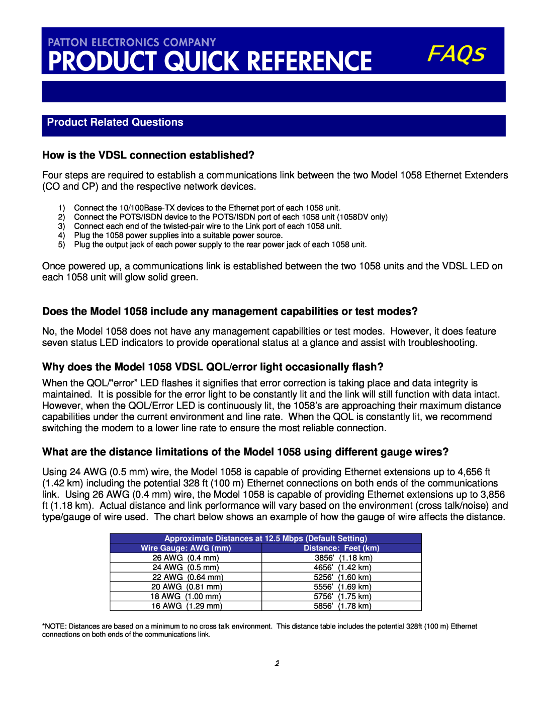
Product Related Questions, How is the VDSL connection established?
Models:
FAQs
1
2
4
4
Download
4 pages
53.84 Kb
1
2
3
4
Page 2
Image 2
Page 1
Page 3
Page 2
Image 2
Page 1
Page 3
Contents
FAQs
Applications
How is the VDSL connection established?
Why does the Model 1058 VDSL QOL/error light occasionally flash?
Product Related Questions
Does the Patton Model 1058 support VLAN?
Will the POTS/ISDN port on the Model 1058DV operate without power?
Does the Model 1058 operate in pairs?
Is the Model 1058 capable of bridging?
What are the power supply options for the Model 1058’s?
How is the Ethernet port configured to accept 10 or 100Base-TX?
Power Supply
What devices typically connect to the Ethernet 10/100Base-TX port?
Top
Page
Image
Contents