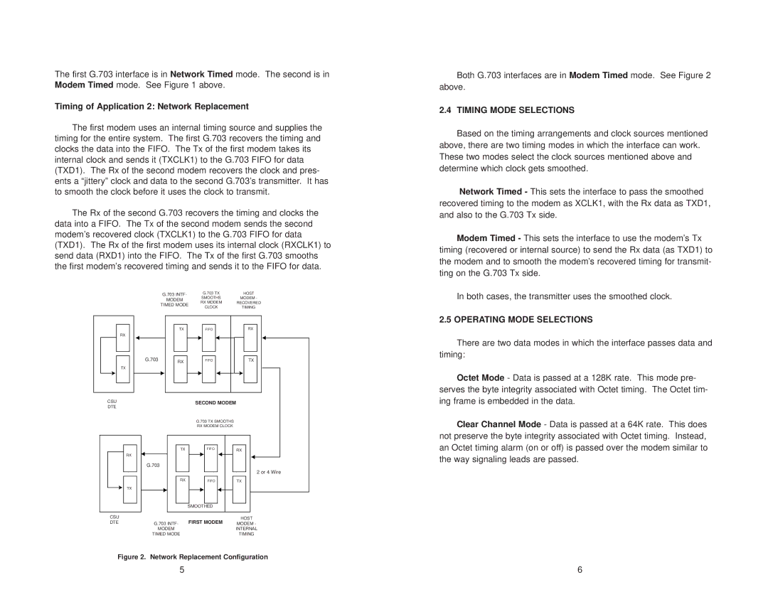
The first G.703 interface is in Network Timed mode. The second is in Modem Timed mode. See Figure 1 above.

Timing of Application 2: Network Replacement

The first modem uses an internal timing source and supplies the timing for the entire system. The first G.703 recovers the timing and clocks the data into the FIFO. The Tx of the first modem takes its internal clock and sends it (TXCLK1) to the G.703 FIFO for data (TXD1). The Rx of the second modem recovers the clock and pres- ents a “jittery” clock and data to the second G.703’s transmitter. It has to smooth the clock before it uses the clock to transmit.

The Rx of the second G.703 recovers the timing and clocks the data into a FIFO. The Tx of the second modem sends the second modem’s recovered clock (TXCLK1) to the G.703 FIFO for data (TXD1). The Rx of the first modem uses its internal clock (RXCLK1) to send data (RXD1) into the FIFO. The Tx of the first G.703 smooths the first modem’s recovered timing and sends it to the FIFO for data.

Both G.703 interfaces are in Modem Timed mode. See Figure 2 above.

2.4 TIMING MODE SELECTIONS

Based on the timing arrangements and clock sources mentioned above, there are two timing modes in which the interface can work. These two modes select the clock sources mentioned above and determine which clock gets smoothed.

Network Timed - This sets the interface to pass the smoothed recovered timing to the modem as XCLK1, with the Rx data as TXD1, and also to the G.703 Tx side.

Modem Timed - This sets the interface to use the modem’s Tx timing (recovered or internal source) to send the Rx data (as TXD1) to the modem and to smooth the modem’s recovered timing for transmit- ting on the G.703 Tx side.

RX

TX

CSU

DTE

G.703 INTF-

G.703 TX

HOST

MODEM

SMOOTHS

MODEM -

RX MODEM

RECOVERED

TIMED MODE

CLOCK

TIMING


TX

FIFO

RX

G.703

RX

FIFO

TX


SECOND MODEM

G.703 TX SMOOTHS

RX MODEM CLOCK

In both cases, the transmitter uses the smoothed clock.

2.5 OPERATING MODE SELECTIONS

There are two data modes in which the interface passes data and timing:

Octet Mode - Data is passed at a 128K rate. This mode pre- serves the byte integrity associated with Octet timing. The Octet tim- ing frame is embedded in the data.

Clear Channel Mode - Data is passed at a 64K rate. This does not preserve the byte integrity associated with Octet timing. Instead, an Octet timing alarm (on or off) is passed over the modem similar to

RX

TX

G.703

TX

FIFO

RX

FIFO

SMOOTHED

RX

TX

2 or 4 Wire

the way signaling leads are passed.

CSU DTE

G.703 INTF- FIRST MODEM

HOST

MODEM -

MODEM

INTERNAL

TIMED MODE

TIMING

Figure 2. Network Replacement Configuration

5

6

Page 4
Image 4
Patton electronic IM 1/F Timing of Application 2 Network Replacement, Timing Mode Selections, Operating Mode Selections

IM 1/F specifications

The Patton Electronics IM 1/F is a cutting-edge network interface device known for its versatility and reliability in data transmission across various communication infrastructures. As a key player in the realm of media conversion, this device is designed to facilitate the seamless integration of analog and digital systems, enhancing connectivity while delivering top-notch performance.

One of the standout features of the IM 1/F is its support for both T1 and E1 interfaces. This dual capability makes it particularly valuable in diverse telecommunications environments, allowing users to easily transition between different communication standards without the need for additional hardware. The device is equipped with a built-in Ethernet interface, promoting hybrid functionality that accommodates modern networking needs.

The IM 1/F employs advanced error correction technologies, which significantly enhance the integrity of data transmission. These features ensure minimal downtime and maximize throughput, making it an ideal choice for businesses that depend on uninterrupted communication channels. Moreover, its ability to handle delays and jitter means that it can maintain high-quality connections, even in challenging network conditions.

Another highlight of the Patton IM 1/F is its compact and rugged design. This makes it suitable for deployment in various environments, from central offices to remote installations. The device supports both standalone and rack-mount configurations, providing flexibility in installation options. Its industrial-grade components are built to withstand harsh operating conditions, ensuring longevity and durability.

The intuitive management interface of the IM 1/F allows for easy configuration and monitoring. Users can access the device via its web-based interface, enabling straightforward adjustments to settings without requiring extensive technical expertise. This user-friendly approach simplifies integration into existing systems, ensuring a smooth operational workflow.

In addition to its robust performance capabilities, the Patton IM 1/F offers comprehensive diagnostic tools. These tools provide insights into line quality and performance metrics, empowering administrators to troubleshoot issues efficiently and optimize network performance.

In conclusion, the Patton Electronics IM 1/F stands out as a versatile and robust solution for businesses in need of reliable data transmission solutions. With its powerful feature set, advanced technologies, and rugged design, it addresses the growing demands of today's interconnected world while ensuring that users can maintain high-quality communication channels with ease.