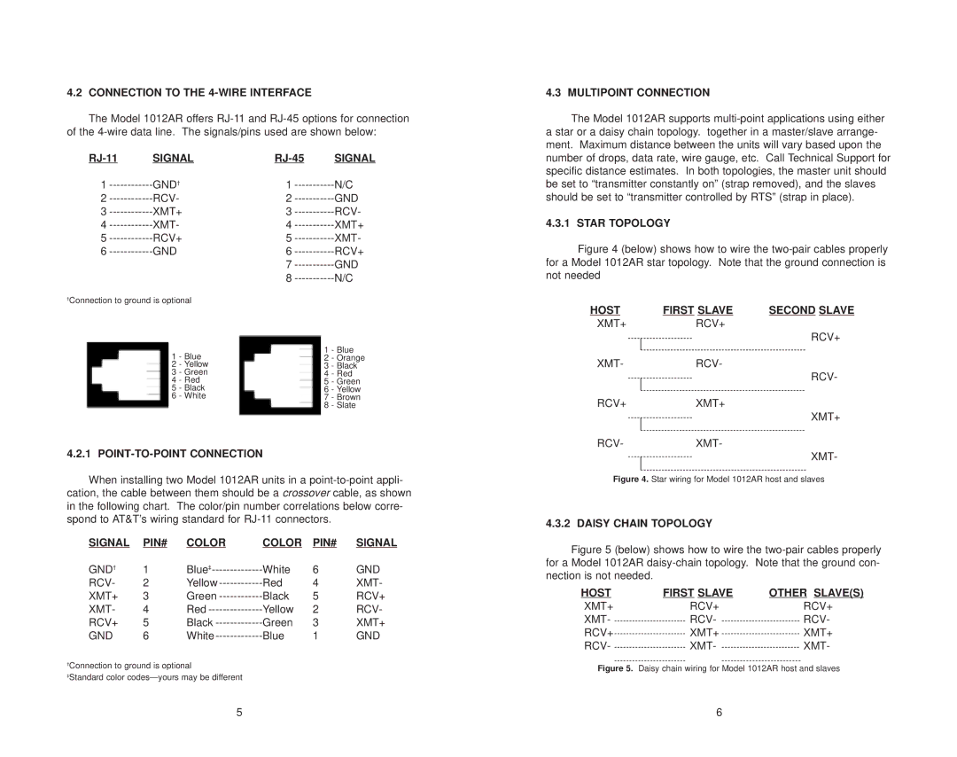
4.2 CONNECTION TO THE 4-WIRE INTERFACE
The Model 1012AR offers
SIGNAL |
| SIGNAL | |||
1 | GND† | 1 | N/C | ||
2 | RCV- | 2 | GND | ||
3 | XMT+ | 3 | RCV- | ||
4 | XMT- | 4 | XMT+ | ||
5 | RCV+ | 5 | XMT- | ||
6 | GND |
| 6 | RCV+ | |
|
|
| 7 | GND | |
|
|
| 8 | N/C | |
†Connection to ground is optional |
|
|
| ||
| 1 | - Blue |
| 1 | - Blue |
|
| 2 | - Orange | ||
| 2 | - Yellow |
| 3 | - Black |
| 3 | - Green |
| 4 | - Red |
| 4 | - Red |
| 5 | - Green |
| 5 | - Black |
| 6 | - Yellow |
| 6 | - White |
| 7 | - Brown |
|
|
|
| 8 | - Slate |
4.2.1 POINT-TO-POINT CONNECTION
When installing two Model 1012AR units in a
SIGNAL | PIN# | COLOR | COLOR | PIN# | SIGNAL |
GND† | 1 | Blue‡ | White | 6 | GND |
RCV- | 2 | Yellow | Red | 4 | XMT- |
XMT+ | 3 | Green | Black | 5 | RCV+ |
XMT- | 4 | Red | Yellow | 2 | RCV- |
RCV+ | 5 | Black | Green | 3 | XMT+ |
GND | 6 | White | Blue | 1 | GND |
†Connection to ground is optional
‡Standard color
4.3 MULTIPOINT CONNECTION
The Model 1012AR supports
4.3.1 STAR TOPOLOGY
Figure 4 (below) shows how to wire the two-pair cables properly for a Model 1012AR star topology. Note that the ground connection is not needed
HOST | FIRST SLAVE | SECOND SLAVE |
XMT+RCV+
RCV+
XMT-RCV-
RCV-
RCV+XMT+
XMT+
RCV-XMT-
XMT-
Figure 4. Star wiring for Model 1012AR host and slaves
4.3.2 DAISY CHAIN TOPOLOGY
Figure 5 (below) shows how to wire the two-pair cables properly for a Model 1012AR daisy-chain topology. Note that the ground con- nection is not needed.
HOST | FIRST SLAVE | OTHER SLAVE(S) |
XMT+ | RCV+ | RCV+ |
XMT- | RCV- | RCV- |
RCV+ | XMT+ | XMT+ |
RCV- | XMT- | XMT- |
Figure 5. Daisy chain wiring for Model 1012AR host and slaves
5 | 6 |