Linking the RF Modules
Despite there being no physical connection (a cable), the RF link device and printer must still be linked so they can communicate. To set up the link:
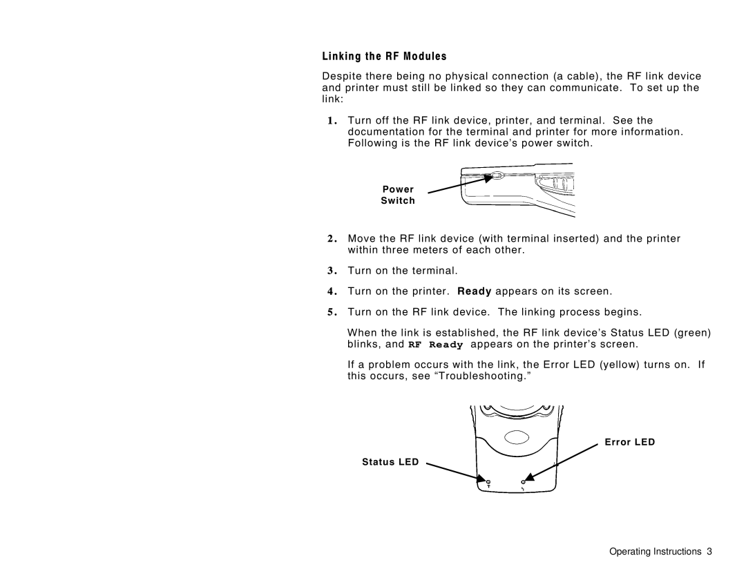
1 . Turn off the RF link device, printer, and terminal. See the documentation for the terminal and printer for more information. Following is the RF link device’s power switch.
Power
Switch
2 . Move the RF link device (with terminal inserted) and the printer within three meters of each other.
3 . Turn on the terminal.
4 . Turn on the printer. Ready appears on its screen.
5 . Turn on the RF link device. The linking process begins.
When the link is established, the RF link device’s Status LED (green) blinks, and RF Ready appears on the printer’s screen.
If a problem occurs with the link, the Error LED (yellow) turns on. If this occurs, see “Troubleshooting.”
Error LED
Status LED
Operating Instructions 3
