
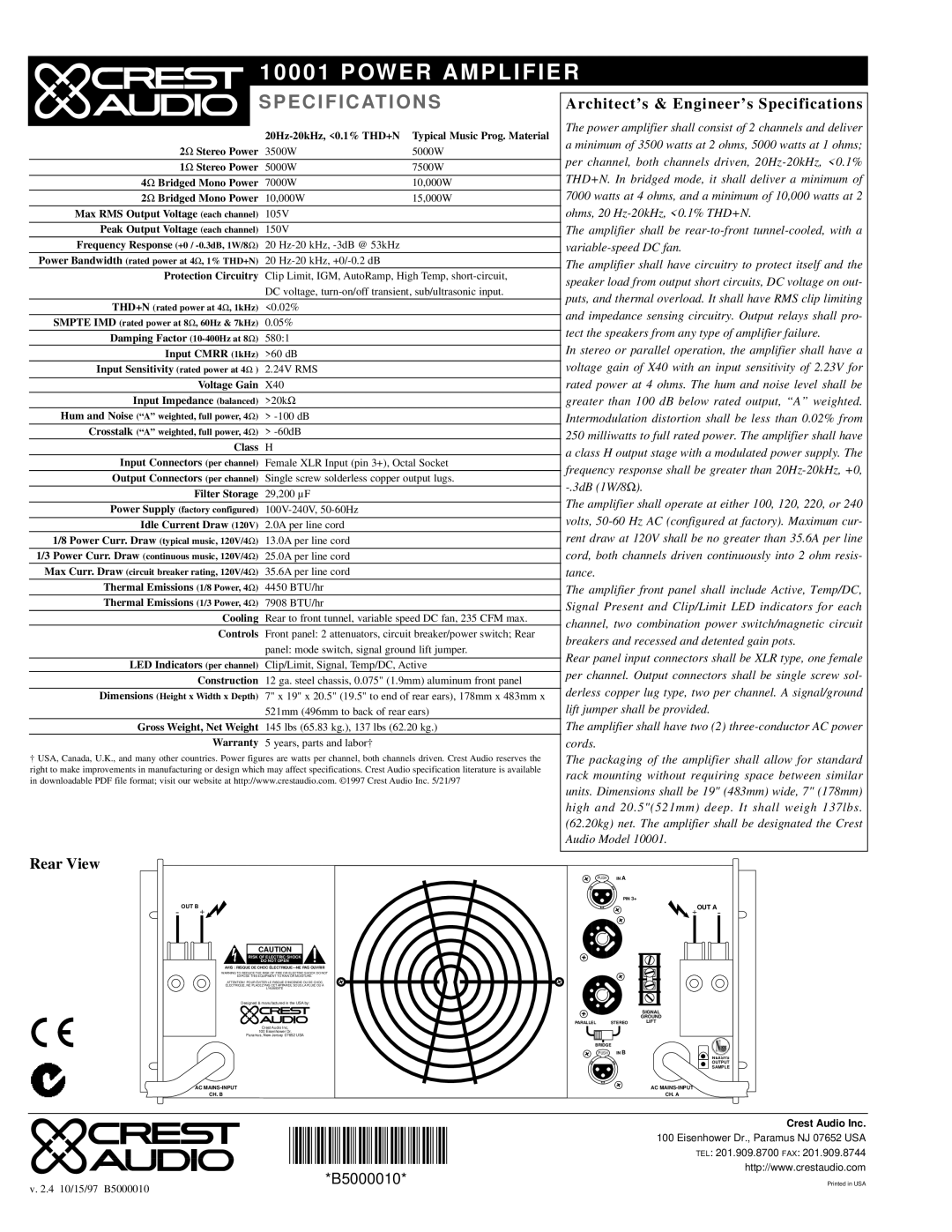
10001 specifications
The Peavey 10001 is a legendary amplifier that has made a significant impact on the music scene since its introduction. Designed primarily for bass guitarists, this powerful amp delivers an impressive combination of performance, versatility, and reliability that appeals to both professional musicians and enthusiasts alike.One of the standout features of the Peavey 10001 is its high power output. With a massive 1000 watts of power, this amplifier can effortlessly drive most speaker cabinets, making it suitable for a wide range of musical environments, from intimate gigs to large arenas. It ensures that players get the rich, full sound they crave while maintaining headroom for dynamic playing styles.
The design of the Peavey 10001 incorporates advanced technology such as Peavey's DDT (Dynamic Duty Cycle Technology) which protects against distortion. This feature allows the amplifier to handle high power levels without compromising sound quality, ensuring that musicians can play with confidence, regardless of volume. The result is a clean, powerful tone that remains articulate, even at high output levels.
The amp also offers a comprehensive EQ system, including a 9-band graphic equalizer, which enables players to shape their sound precisely. This feature is invaluable for achieving the desired tone in various musical genres, whether it’s rock, jazz, or funk. Additionally, the adjustable mids and treble control allow users to enhance the tonal characteristics of their bass, making it a highly customizable solution.
For connectivity, the Peavey 10001 is equipped with multiple input options, including a dedicated input for active and passive instruments. This versatility ensures that no matter the player's gear, they can achieve optimal performance. The amplifier also features an effects loop, allowing musicians to integrate pedals and effects seamlessly into their setup, further expanding their creative possibilities.
Another notable characteristic of the Peavey 10001 is its rugged construction. Built to withstand the rigors of touring, the durable casing and reliable components ensure longevity and consistent performance over time. The amp's lightweight design means it is also more portable, a critical consideration for gigging musicians.
In summary, the Peavey 10001 stands out as a powerful, reliable, and versatile bass amplifier. With its extensive features, cutting-edge technology, and durable design, it continues to be an excellent choice for bass players looking to elevate their sound and performance quality in a variety of musical settings.