Front Panel
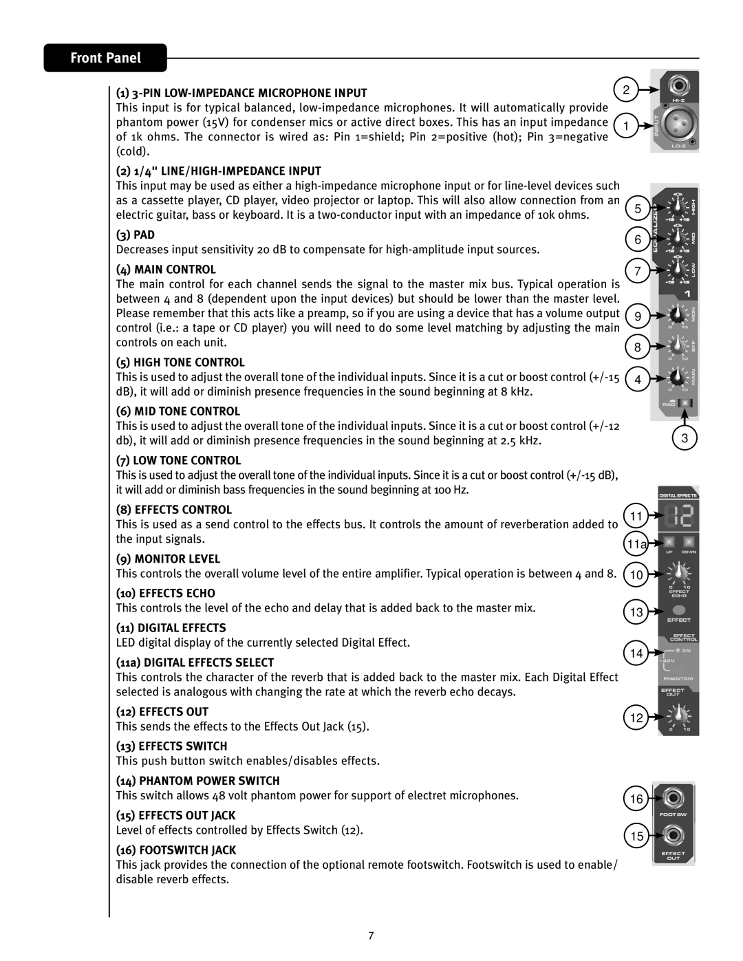
(1) | 2 |
This input is for typical balanced, |
| |
phantom power (15V) for condenser mics or active direct boxes. This has an input impedance | 1 | |
of 1k ohms. The connector is wired as: Pin 1=shield; Pin 2=positive (hot); Pin 3=negative | ||
| ||
(cold). |
|
(2) 1/4" LINE/HIGH-IMPEDANCE INPUT
This input may be used as either a
(3) PAD
Decreases input sensitivity 20 dB to compensate for
5
6
(4) MAIN CONTROL
The main control for each channel sends the signal to the master mix bus. Typical operation is between 4 and 8 (dependent upon the input devices) but should be lower than the master level. Please remember that this acts like a preamp, so if you are using a device that has a volume output control (i.e.: a tape or CD player) you will need to do some level matching by adjusting the main controls on each unit.
(5) HIGH TONE CONTROL
This is used to adjust the overall tone of the individual inputs. Since it is a cut or boost control
(6) MID TONE CONTROL
This is used to adjust the overall tone of the individual inputs. Since it is a cut or boost control
(7) LOW TONE CONTROL
This is used to adjust the overall tone of the individual inputs. Since it is a cut or boost control
(8) EFFECTS CONTROL
This is used as a send control to the effects bus. It controls the amount of reverberation added to the input signals.
(9) MONITOR LEVEL
This controls the overall volume level of the entire amplifier. Typical operation is between 4 and 8.
(10) EFFECTS ECHO
This controls the level of the echo and delay that is added back to the master mix.
(11) DIGITAL EFFECTS
LED digital display of the currently selected Digital Effect.
(11a) DIGITAL EFFECTS SELECT
This controls the character of the reverb that is added back to the master mix. Each Digital Effect selected is analogous with changing the rate at which the reverb echo decays.
7
9
8
4
3
11![]()
11a ![]()
10
13
14
(12) EFFECTS OUT
This sends the effects to the Effects Out Jack (15).
(13) EFFECTS SWITCH
This push button switch enables/disables effects.
(14) PHANTOM POWER SWITCH
This switch allows 48 volt phantom power for support of electret microphones.
(15) EFFECTS OUT JACK
Level of effects controlled by Effects Switch (12).
(16) FOOTSWITCH JACK
This jack provides the connection of the optional remote footswitch. Footswitch is used to enable/ disable reverb effects.
12
16 ![]()
15
