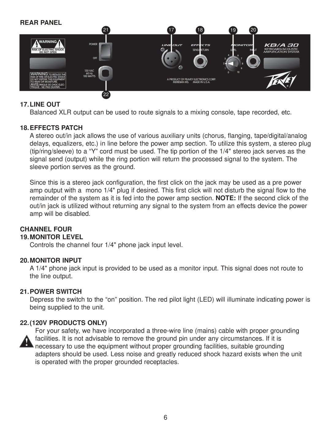
REAR PANEL
21 | 17 | 18 | 19 | 20 | ||||||
|
|
|
|
|
|
|
|
|
|
|
|
|
|
|
|
|
|
|
|
|
|
|
|
|
|
|
|
|
|
|
|
|
|
|
|
|
|
|
|
|
|
|
|
|
|
|
|
|
|
|
|
|
|
|
|
|
|
|
|
|
|
|
|
|
|
|
|
|
|
|
|
|
|
|
|
|
|
|
|
|
|
|
|
|
|
|
|
|
|
|
|
|
|
|
|
|
|
|
|
|
|
|
|
|
|
|
|
|
|
|
|
|
|
|
|
|
|
|
|
|
|
|
|
|
|
|
|
|
|
|
|
|
|
|
|
|
|
|
|
|
|
|
|
|
|
|
|
|
|
|
|
|
|
|
|
|
|
|
|
|
|
|
|
|
|
|
|
|
|
|
|
|
|
|
|
|
|
|
|
|
|
|
|
|
|
|
|
|
|
|
|
|
|
|
|
|
|
|
|
|
|
|
|
|
|
|
|
|
|
|
|
|
|
|
|
|
|
|
|
|
|
|
|
|
|
|
|
|
|
|
|
|
|
|
|
|
|
|
|
|
|
|
|
|
|
|
|
|
|
|
|
|
22
17.LINE OUT
Balanced XLR output can be used to route signals to a mixing console, tape recorded, etc.
18.EFFECTS PATCH
A stereo out/in jack allows the use of various auxiliary units (chorus, flanging, tape/digital/analog delays, equalizers, etc.) in line before the power amp section. To utilize this system, a stereo plug (tip/ring/sleeve) to a “Y” cord must be used. The tip portion of the 1/4" stereo jack serves as the signal send (output) while the ring portion will return the processed signal to the system. The sleeve portion serves as the ground.
Since this is a stereo jack configuration, the first click on the jack may be used as a pre power amp output with a mono 1/4" plug if desired. This first click will not disturb the signal flow to the remainder of the system as it is fed into the power amp section. NOTE: If the second click of the out/in jack is utilized without returning any signal to the system from an effects device the power amp will be disabled.
CHANNEL FOUR
19.MONITOR LEVEL
Controls the channel four 1/4" phone jack input level.
20.MONITOR INPUT
A 1/4" phone jack input is provided to be used as a monitor input. This signal does not route to the line output.
21.POWER SWITCH
Depress the switch to the “on” position. The red pilot light (LED) will illuminate indicating power is being supplied to the unit.
22.(120V PRODUCTS ONLY)
For your safety, we have incorporated a
6
