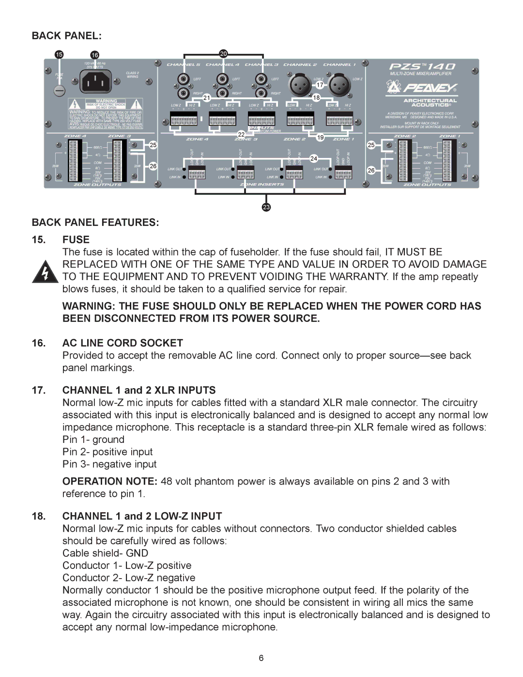
BACK PANEL:
15 | 16 | 20 |
|
| 17 |
| 21 | 18 |
| 22 | 19 |
|
| |
25 |
| 25 |
|
| 24 |
26 |
26 |
23
BACK PANEL FEATURES:
15.FUSE
The fuse is located within the cap of fuseholder. If the fuse should fail, IT MUST BE REPLACED WITH ONE OF THE SAME TYPE AND VALUE IN ORDER TO AVOID DAMAGE TO THE EQUIPMENT AND TO PREVENT VOIDING THE WARRANTY. If the amp repeatly blows fuses, it should be taken to a qualified service for repair.
WARNING: THE FUSE SHOULD ONLY BE REPLACED WHEN THE POWER CORD HAS BEEN DISCONNECTED FROM ITS POWER SOURCE.
16.AC LINE CORD SOCKET
Provided to accept the removable AC line cord. Connect only to proper sourceÑsee back panel markings.
17.CHANNEL 1 and 2 XLR INPUTS
Normal
Pin 2- positive input Pin 3- negative input
OPERATION NOTE: 48 volt phantom power is always available on pins 2 and 3 with reference to pin 1.
18.CHANNEL 1 and 2 LOW-Z INPUT
Normal
Cable shield- GND Conductor 1-
Normally conductor 1 should be the positive microphone output feed. If the polarity of the associated microphone is not known, one should be consistent in wiring all mics the same way. Again the circuitry associated with this input is electronically balanced and is designed to accept any normal
6
