SERVICE MENU

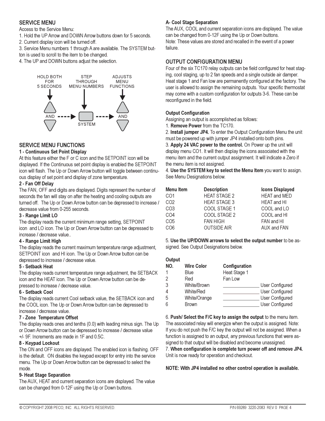
Access to the Service Menu:

1.Hold the UP Arrow and DOWN Arrow buttons down for 5 seconds.

2.Current display icon will be turned off.

3.Service Menu numbers 1 through A are available. The SYSTEM but- ton is used to scroll to the item to be changed.

4.The UP and DOWN buttons adjust the selection.

HOLD BOTH

STEP

ADJUSTS

FOR

THROUGH

MENU

5 SECONDS

MENU NUMBERS

FUNCTIONS

AND

AND


SYSTEM

SERVICE MENU FUNCTIONS

1 - Continuous Set Point Display

At this feature either the F or C icon and the SETPOINT icon will be displayed. If the Continuous set point display is enabled the SETPOINT icon will flash. The Up or Down Arrow button will toggle between continu- ous display of set point and display of zone temperature.

2 - Fan Off Delay

The FAN, OFF and digits are displayed. Digits represent the number of seconds the fan will stay on after the heating and cooling outputs are turned off. The Up or Down Arrow button can be depressed to increase / decrease value from 0-255 seconds.

3 - Range Limit LO

The display reads the current minimum range setting, SETPOINT icon and LO icon. The Up or Down Arrow button can be depressed to increase / decrease value..

4 - Range Limit High

The display reads the current maximum temperature range adjustment, SETPOINT icon and HI icon. The Up or Down Arrow button can be depressed to increase / decrease value.

5 - Setback Heat

The display reads current temperature range adjustment, the SETBACK icon and the HEAT icon. The Up or Down Arrow button can be de- pressed to increase / decrease value.

6 - Setback Cool

The display reads current Cool setback value, the SETBACK icon and the COOL icon. The Up or Down Arrow button can be depressed to increase / decrease value.

7 - Zone Temperature Offset

The display reads ones and tenths (0.0) with leading minus sign. The Up or Down Arrow button can be depressed to increase / decrease value +/- 9F. Increments are made in 1F and 0.5C.

8 - Keypad Lockout

The ON and OFF icons are displayed. The enabled icon is flashing. OFF is the default. ON disables the keypad except for entry into the service menu. The Up or Down Arrow button can be depressed to select the mode.

9- Heat Stage Separation

The AUX, HEAT and current separation icons are displayed. The value can be changed from 0-12F using the Up or Down buttons.

A- Cool Stage Separation

The AUX, COOL and current separation icons are displayed. The value can be changed from 0-12F using the Up or Down buttons.

Note: These values are stored and recalled in the event of a power failure.

OUTPUT CONFIGURATION MENU

Four of the six TC170 relay outputs can be field configured for heat stag- ing, cool staging, up to 2 fan speeds and a single outside air damper. Heat stage 1 and Fan low are permanently configured at the factory. The user is allowed to assign the remaining outputs. Your specific thermostat may come with a custom configuration for outputs 3-6. These can be reconfigured in the field.

Output Configuration

Assigning an output is accomplished as follows:

1.Remove Power from the TC170.

2.Install jumper JP4. To enter the Output Configuration Menu the unit

must be powered up with jumper JP4 installed onto both pins.

3.Apply 24 VAC power to the control. On Power up the unit will display menu CO1. It will then display the icons associated with the menu item and the current output assignment. It will indicate a Zero if the menu item is not assigned.

4.Use the SYSTEM key to select the Menu Item you want to assign. See Menu Designations below.

Menu Item

Description

Icons Displayed

CO1

HEAT STAGE 2

HEAT and MED

CO2

HEAT STAGE 3

HEAT and HI

CO3

COOL STAGE 1

COOL and LO

CO4

COOL STAGE 2

COOL and HI

CO5

FAN HIGH

FAN and HI

CO6

OUTSIDE AIR

AUX and FAN

5.Use the UP/DOWN arrows to select the output number to be as- signed. See Output Designations below.

Output


NO.

Wire Color

Configuration

1

Blue

Heat Stage 1

2

Red

Fan Low

3

White/Brown

_______________ User Configured

4

White/Red

_______________ User Configured

5

White/Orange

_______________ User Configured

6

Brown

_______________ User Configured

6.Push/ Select the F/C key to assign the output to the menu item. The associated relay will energize when the output is assigned. Note:

If you do not push the F/C key the output will not be assigned. When a function is assigned to an output, any previous functions that were as- signed to that output will be disabled and become unassigned.

7.When configuration is complete turn power off and remove JP4.

Unit is now ready for operation and checkout.

NOTE: With JP4 installed no other control operation is available.

© COPYRIGHT 2008 PECO, INC. ALL RIGHTS RESERVED.

P/N 69289 3220-2083 REV 0 PAGE 4

Page 4
Image 4
Pecoware TC170 manual Service Menu Functions, Output Configuration Menu

TC170 specifications

Pecoware TC170 is an innovative touch computer designed for various industrial applications, offering robust features and cutting-edge technology to meet the demands of modern businesses. With a focus on durability, performance, and user-friendly interfaces, the TC170 stands out in the market as a reliable solution for various operational needs.

One of the main features of the Pecoware TC170 is its impressive touchscreen display. The device comes equipped with a 17-inch high-resolution display that provides excellent visibility, even in challenging lighting conditions. This makes it ideal for environments such as factories and warehouses where bright lights or glare might interfere with visibility. The touchscreen is designed for ease of use, supporting multi-touch functionality for a more intuitive user experience.

The TC170 is built on a powerful processor platform, ensuring fast response times and efficient multitasking. It typically features an Intel Celeron or Core i-series processor, allowing it to handle various applications seamlessly. This performance is further complemented by ample RAM options, which enable the device to run multiple applications without compromising speed or efficiency.

In terms of connectivity, the Pecoware TC170 excels with multiple ports, including USB, Ethernet, and serial connections, allowing easy integration with various peripherals and automation systems. This versatility makes it suitable for different sectors, including manufacturing, logistics, and retail.

Durability is another defining characteristic of the TC170. It is designed to withstand the rigors of industrial environments, featuring a rugged chassis and IP-rated protection against dust and water. This resilience ensures that the device can operate reliably in harsh conditions, minimizing downtime and maintenance costs.

Additionally, the TC170 supports various operating systems, including Windows and Linux, providing flexibility for businesses to choose the software that best meets their operational needs. This adaptability is crucial in a rapidly evolving technological landscape, allowing organizations to stay competitive.

With its blend of technology, durability, and functionality, the Pecoware TC170 is an ideal solution for businesses looking to enhance productivity and streamline operations. Its user-friendly design, coupled with robust performance features, positions it as a frontrunner in the touch computer market. Whether for data entry, inventory management, or real-time processing, the TC170 is designed to meet the diverse needs of modern enterprises, making it a valuable investment for the future.