Attaching Adapter Plate to Wall Plate
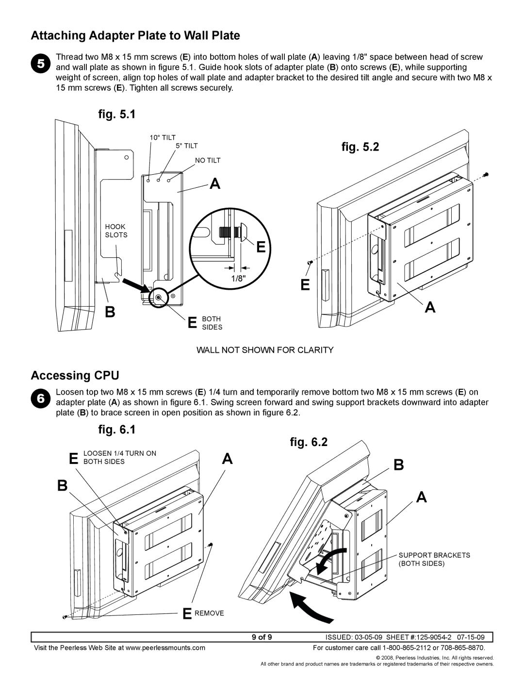
5 | Thread two M8 x 15 mm screws (E) into bottom holes of wall plate (A) leaving 1/8" space between head of screw |
and wall plate as shown in figure 5.1. Guide hook slots of adapter plate (B) onto screws (E), while supporting |
weight of screen, align top holes of wall plate and adapter bracket to the desired tilt angle and secure with two M8 x 15 mm screws (E). Tighten all screws securely.
fig. 5.1
10° TILT
5° TILT | fig. 5.2 |
| |
NO TILT |
|
A |
|
| HOOK |
|
|
| SLOTS |
| E |
|
|
| |
|
| 1/8" | E |
|
|
| |
| B | E SIDESBOTH | A |
|
| ||
|
| wall not shown for clarity | |
Accessing CPU |
|
| |
6 | Loosen top two M8 x 15 mm screws (E) 1/4 turn and temporarily remove bottom two M8 x 15 mm screws (E) on | ||
adapter plate (A) as shown in figure 6.1. Swing screen forward and swing support brackets downward into adapter | |||
plate (B) to brace screen in open position as shown in figure 6.2.
E
B
fig. 6.1
Loosen 1/4 turn on both sides
fig. 6.2
AB
A
support brackets (both sides)
E remove |
|
9 of 9 | ISSUED: |
Visit the Peerless Web Site at www.peerlessmounts.com | For customer care call |
© 2008, Peerless Industries, Inc. All rights reserved. All other brand and product names are trademarks or registered trademarks of their respective owners.