+ -
|
| 10 PINS |
|
| PIN 5 + |
| + | PIN 4 - |
|
| |
| - |
|
|
| FIXED CAMERA |
|
| 8 PINS |
MONITOR |
| UTP |
|
|
|
|
|
|
| VIDEO |
|
|
|
|
|
|
| |
|
|
|
|
|
|
|
|
|
|
|
|
|
|
| TW3032P |
1 | 2 | 3 | 4 | 5 | 6 | 7 | 8 | 9 | 10 | 11 | 12 | 13 | 14 | 15 | 16 |
17 | 18 | 19 | 20 | 21 | 22 | 23 | 24 | 25 | 26 | 27 | 28 | 29 | 30 | 31 | 32 |
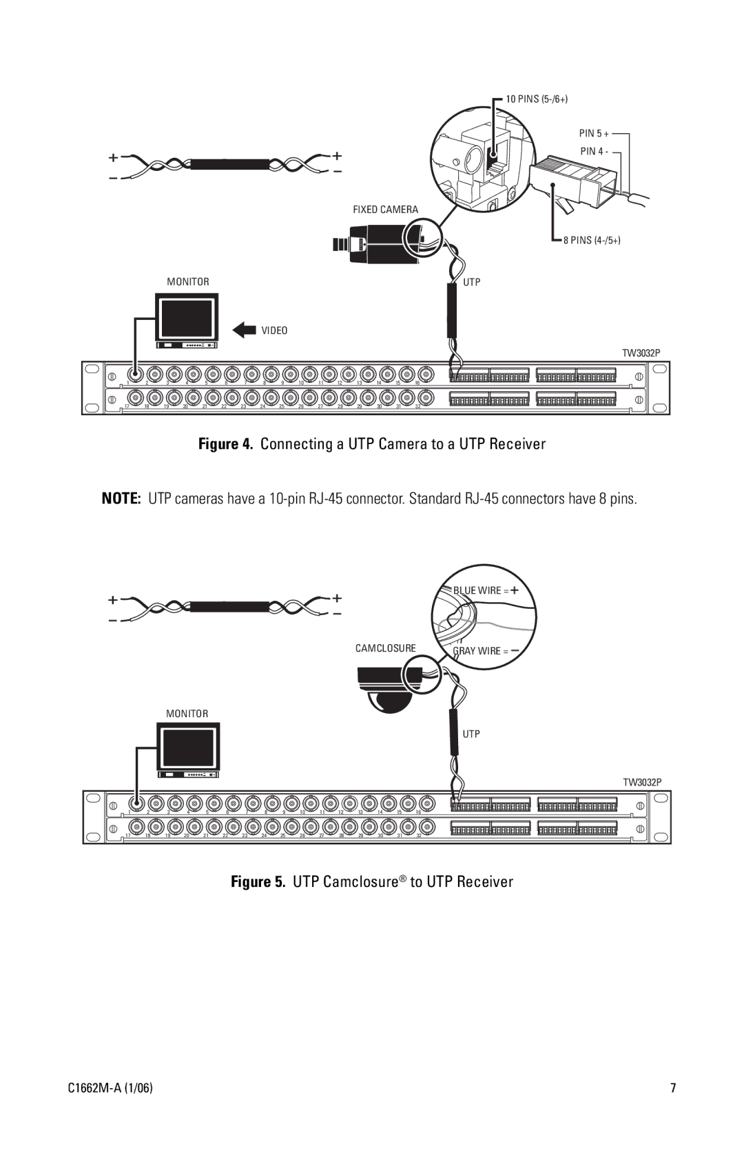
Figure 4. Connecting a UTP Camera to a UTP Receiver
NOTE: UTP cameras have a
+ -
+
-
BLUE WIRE =
CAMCLOSURE | GRAY WIRE = |
MONITOR
UTP
|
|
|
|
|
|
|
|
|
|
|
|
|
|
| TW3032P |
1 | 2 | 3 | 4 | 5 | 6 | 7 | 8 | 9 | 10 | 11 | 12 | 13 | 14 | 15 | 16 |
17 | 18 | 19 | 20 | 21 | 22 | 23 | 24 | 25 | 26 | 27 | 28 | 29 | 30 | 31 | 32 |
Figure 5. UTP Camclosure® to UTP Receiver
7 |
