2.0 SCOPE
The information contained within this manual covers the AZL (Azmith and Elevation
3.0 DESCRIPTION
The AZL is used to provide a visual
The AZL consists of two easily read Simpson meters mounted on the front panel of the unit along with the power switch and power on indicator.
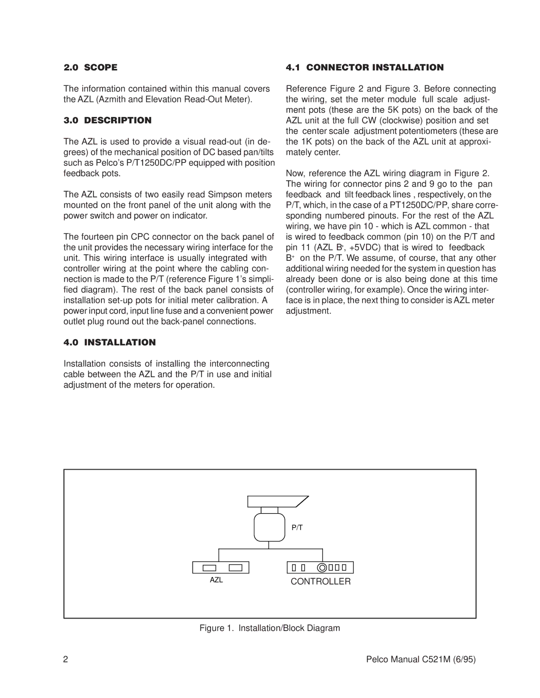
The fourteen pin CPC connector on the back panel of the unit provides the necessary wiring interface for the unit. This wiring interface is usually integrated with controller wiring at the point where the cabling con- nection is made to the P/T (reference Figure 1's simpli- fied diagram). The rest of the back panel consists of installation
4.0 INSTALLATION
Installation consists of installing the interconnecting cable between the AZL and the P/T in use and initial adjustment of the meters for operation.
4.1 CONNECTOR INSTALLATION
Reference Figure 2 and Figure 3. Before connecting the wiring, set the meter module “full scale” adjust- ment pots (these are the 5K pots) on the back of the AZL unit at the full CW (clockwise) position and set the “center scale” adjustment potentiometers (these are the 1K pots) on the back of the AZL unit at approxi- mately center.
Now, reference the AZL wiring diagram in Figure 2. The wiring for connector pins 2 and 9 go to the “pan feedback” and “tilt feedback lines”, respectively, on the P/T, which, in the case of a PT1250DC/PP, share corre- sponding numbered pinouts. For the rest of the AZL wiring, we have pin 10 - which is AZL common - that is wired to feedback common (pin 10) on the P/T and pin 11 (AZL B+, +5VDC) that is wired to “feedback B+” on the P/T. We assume, of course, that any other additional wiring needed for the system in question has already been done or is also being done at this time (controller wiring, for example). Once the wiring inter- face is in place, the next thing to consider is AZL meter adjustment.
P/T
AZLCONTROLLER
Figure 1. Installation/Block Diagram
2 | Pelco Manual C521M (6/95) |