LRD41C-CONNKIT
for LRD41C21-*/LRD41C22-* Receiver/Driver C559M (5/97)
Installation Instructions
The LRD41C-CONNKIT is required to enable alarm and auxiliary functions of the receiver/driver.
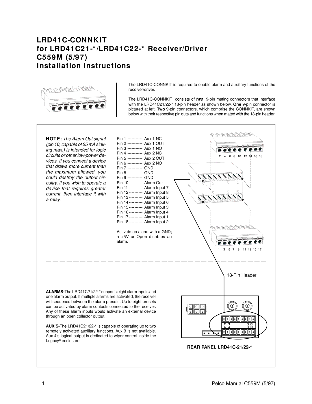
The LRD41C-CONNKIT consists of two 9-pin mating connectors that interface with the LRD41C21/22-* 18-pin header as shown below. One 9-pin connector is pictured at left. Two 9-pin connectors, which comprise the CONNKIT, are shown below with their respective pin outs and functions when mated with the 18-pin header.
NOTE: The Alarm Out signal (pin 10, capable of 25 mA sink- ing max.) is intended for logic circuits or other low-power de- vices. If you connect a device that draws more current than the maximum allowed, you could destroy the output cir- cuitry. If you wish to operate a device that requires greater current, then interface it with a relay.
Pin 1 ----------- | Aux 1 NC |
Pin 2 ----------- | Aux 1 OUT |
Pin 3 ----------- | Aux 1 NO |
Pin 4 ----------- | Aux 2 NC |
Pin 5 ----------- | Aux 2 OUT |
Pin 6 ----------- | Aux 2 NO |
Pin 7 ----------- | GND |
Pin 8 ----------- | GND |
Pin 9 ----------- | GND |
Pin 10 ---------- | Alarm Out |
Pin 11 ---------- | Alarm Input 7 |
Pin 12 ---------- | Alarm Input 8 |
Pin 13 ---------- | Alarm Input 5 |
Pin 14 ---------- | Alarm Input 6 |
Pin 15 ---------- | Alarm Input 3 |
Pin 16 ---------- | Alarm Input 4 |
Pin 17 ---------- | Alarm Input 1 |
Pin 18 ---------- | Alarm Input 2 |
Activate an alarm with a GND; a +5V or Open disables an alarm.
18-Pin Header
ALARMS-The LRD41C21/22-* supports eight alarm inputs and one alarm output. If multiple alarms are activated, the receiver will sequence between the alarm presets. Up to eight presets can be activated by alarm contacts connected to the receiver. Any of these alarm inputs would activate an external device through an open collector output.
AUX’S-The LRD41C21/22-* is capable of operating up to two remotely activated auxiliary functions. Aux 3 is not available. Aux 4’s logical output is dedicated to wiper control inside the Legacy® enclosure.
REAR PANEL LRD41C-21/22-*
1 | Pelco Manual C559M (5/97) |