Preparing the Cabinet – Single Door Freezer
Uncrating and Inspection
Remove all crating material before operating. Carefully inspect cabinet for hidden damage. If damage is discovered, file your claim immediately with the transport company. Perlick is not responsible for damage in transit.
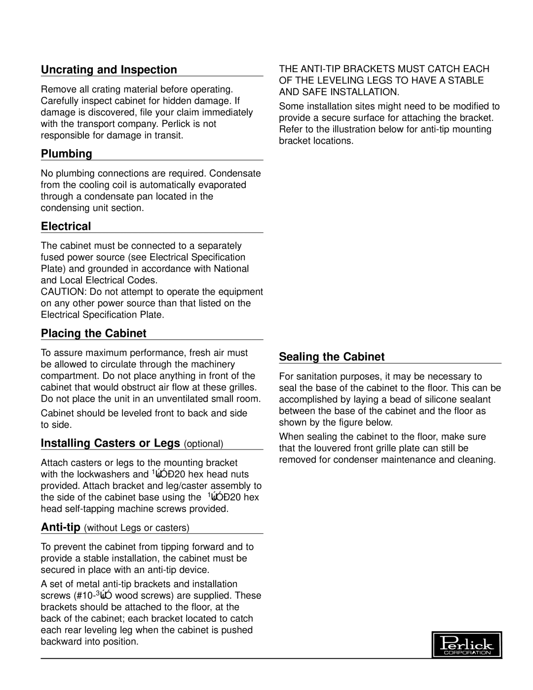
THE
Some installation sites might need to be modified to provide a secure surface for attaching the bracket. Refer to the illustration below for
Plumbing
No plumbing connections are required. Condensate from the cooling coil is automatically evaporated through a condensate pan located in the condensing unit section.
Electrical
The cabinet must be connected to a separately fused power source (see Electrical Specification Plate) and grounded in accordance with National and Local Electrical Codes.
CAUTION: Do not attempt to operate the equipment on any other power source than that listed on the Electrical Specification Plate.
NOTE: Do not extend leveler leg more than 3/4” out of base. Do not shim or pad to obtain levelness.
![]() 1 1/2”
1 1/2”
20 7/8”
7/16”
Surface Ø 3/8” mounts to floor.
Cabinet must have at least 5/16” clearance from floor to accomodate brackets.
Shown with leg leveler engaged in
Placing the Cabinet
To assure maximum performance, fresh air must be allowed to circulate through the machinery compartment. Do not place anything in front of the cabinet that would obstruct air flow at these grilles. Do not place the unit in an unventilated small room.
Cabinet should be leveled front to back and side to side.
Installing Casters or Legs (optional)
Attach casters or legs to the mounting bracket with the lockwashers and
To prevent the cabinet from tipping forward and to provide a stable installation, the cabinet must be secured in place with an
A set of metal
TOP VIEW
Sealing the Cabinet
For sanitation purposes, it may be necessary to seal the base of the cabinet to the floor. This can be accomplished by laying a bead of silicone sealant between the base of the cabinet and the floor as shown by the figure below.
When sealing the cabinet to the floor, make sure that the louvered front grille plate can still be removed for condenser maintenance and cleaning.
CABINET
BEAD SILICON
SEALER (RTV)
FLOOR
Perlick is committed to continuous improvement. Therefore, we reserve the right to change specifications without prior notice.
3 | Form No. Z2255 |
| Rev. 08.22.06 |