F24S F24N specifications
The Perlick F24S and F24N are innovative cooling solutions designed to meet the needs of modern kitchens, bars, and restaurants. Renowned for their reliability and efficiency, these models have carved a niche in the market for commercial refrigeration.The Perlick F24S stands out with its sleek, stainless steel exterior, making it not only functional but also aesthetically pleasing. Its design allows it to fit seamlessly into any environment while offering robust performance. The unit is engineered to hold temperatures between 33°F and 36°F, ensuring that beverages and perishable items are kept fresh and at optimal serving temperature.
On the other hand, the F24N model shares many of its features with the F24S, but it is specifically designed for environments where a narrower footprint is required. This compact design does not compromise on storage capacity, allowing operators to maximize their available space while still accommodating a variety of items, from craft beer to bottled beverages.
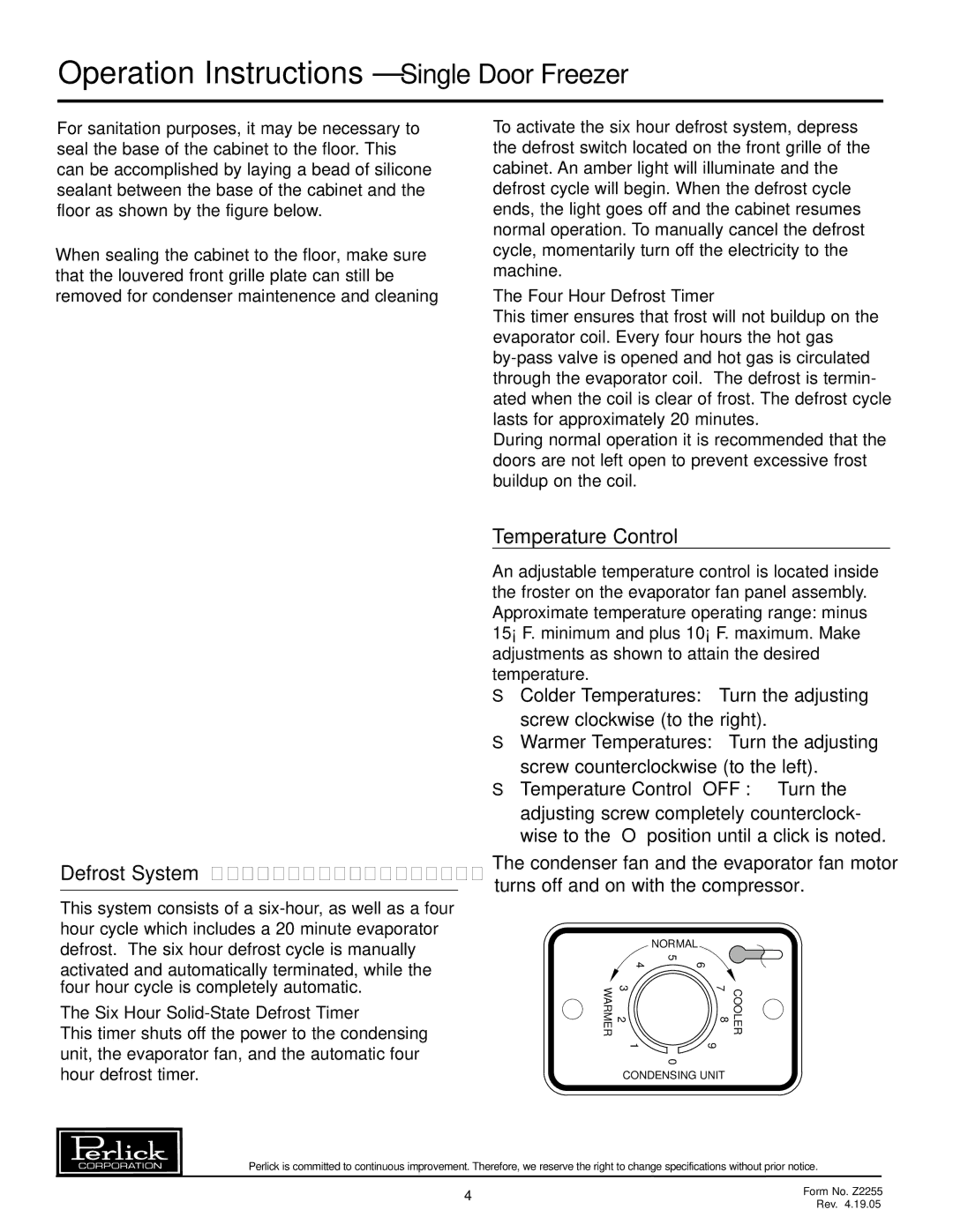
Both models are equipped with advanced cooling technology, which includes a forced air refrigeration system that provides rapid temperature recovery even during peak usage. This technology helps to reduce energy consumption and ensures the integrity of products stored within. Additionally, the units feature an automatic defrost system, which minimizes the need for manual maintenance and enhances overall efficiency.
One notable characteristic of the Perlick F24S and F24N is their versatile shelving options. The adjustable shelving allows for customized storage solutions and accommodates a wide range of bottle sizes and shapes. This flexibility is crucial for busy operators who require quick access to various products.
The interior is designed with LED lighting, which not only enhances visibility but also provides energy efficiency compared to traditional lighting options. This lighting system highlights the contents of the unit, making it easier for bartenders and staff to find items quickly during service.
Moreover, both models are equipped with a user-friendly digital controller that grants users precise temperature management, ensuring optimal performance at all times. This feature includes alarms for temperature fluctuations, adding an extra layer of security for valuable inventory.
Overall, the Perlick F24S and F24N models are ideal solutions for anyone seeking reliable, efficient, and stylish refrigeration options for commercial use. With their advanced technologies and thoughtful design, these units continue to set a high standard in the industry.

