QUICK USE AND INSTALLATION GUIDE
TABLE OF CONTENTS
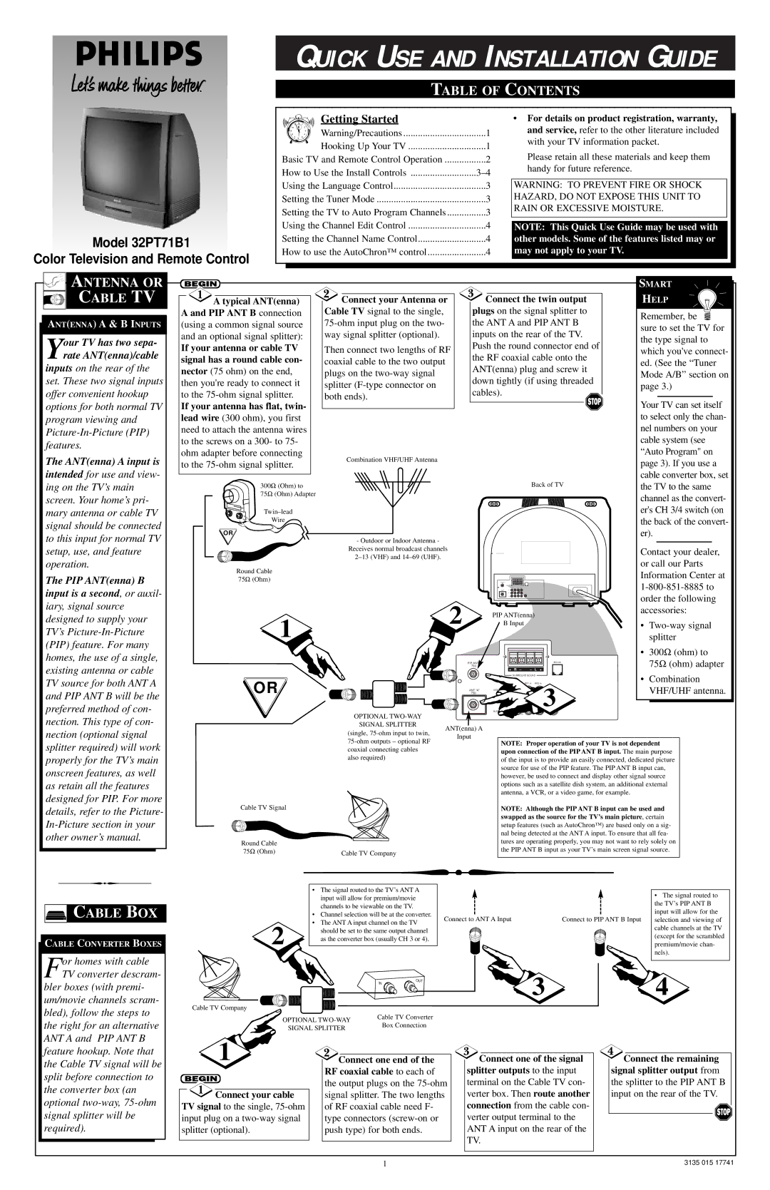
Model 32PT71B1
Color Television and Remote Control
11 12 | 1 |
| Getting Started |
|
10 |
| 2 | Warning/Precautions | 1 |
9 |
| 3 | ||
8 |
| 4 |
|
|
75
6
Hooking Up Your TV | 1 |
Basic TV and Remote Control Operation | 2 |
How to Use the Install Controls | |
Using the Language Control | 3 |
Setting the Tuner Mode | 3 |
Setting the TV to Auto Program Channels | 3 |
Using the Channel Edit Control | 4 |
Setting the Channel Name Control | 4 |
How to use the AutoChron™ control | 4 |
•For details on product registration, warranty, and service, refer to the other literature included with your TV information packet.
Please retain all these materials and keep them handy for future reference.
WARNING: TO PREVENT FIRE OR SHOCK HAZARD, DO NOT EXPOSE THIS UNIT TO RAIN OR EXCESSIVE MOISTURE.
NOTE: This Quick Use Guide may be used with other models. Some of the features listed may or may not apply to your TV.


 ANTENNA OR CABLE TV
ANT(ENNA) A & B INPUTS
Your TV has two sepa- rate ANT(enna)/cable
inputs on the rear of the set. These two signal inputs offer convenient hookup options for both normal TV program viewing and
The ANT(enna) A input is
intended for use and view- ing on the TV’s main screen. Your home’s pri- mary antenna or cable TV signal should be connected to this input for normal TV setup, use, and feature operation.
The PIP ANT(enna) B
input is a second, or auxil- iary, signal source designed to supply your TV’s
|
|
| SMART | |
A typical ANT(enna) | Connect your Antenna or | Connect the twin output | HELP | |
A and PIP ANT B connection | Cable TV signal to the single, | plugs on the signal splitter to | Remember, be | |
(using a common signal source | the ANT A and PIP ANT B | |||
sure to set the TV for | ||||
and an optional signal splitter): | way signal splitter (optional). | inputs on the rear of the TV. | ||
the type signal to | ||||
If your antenna or cable TV | Then connect two lengths of RF | Push the round connector end of | ||
which you've connect- | ||||
the RF coaxial cable onto the | ||||
signal has a round cable con- | coaxial cable to the two output | ed. (See the “Tuner | ||
ANT(enna) plug and screw it | ||||
nector (75 ohm) on the end, | plugs on the | Mode A/B” section on | ||
down tightly (if using threaded | ||||
then you're ready to connect it | splitter | page 3.) | ||
cables). | ||||
to the | both ends). | Your TV can set itself | ||
If your antenna has flat, twin- |
|
| ||
lead wire (300 ohm), you first |
|
| to select only the chan- | |
need to attach the antenna wires |
|
| nel numbers on your | |
to the screws on a 300- to 75- |
|
| cable system (see | |
ohm adapter before connecting | Combination VHF/UHF Antenna |
| “Auto Program" on | |
to the |
| page 3). If you use a | ||
|
| |||
|
|
| cable converter box, set | |
300Ω (Ohm) to |
| Back of TV | the TV to the same | |
75Ω (Ohm) Adapter |
|
| channel as the convert- | |
|
|
| ||
|
| er's CH 3/4 switch (on | ||
Wire |
|
| the back of the convert- | |
OR |
|
| er). |
| - Outdoor or Indoor Antenna - |
|
|
|
|
|
|
| Receives normal broadcast channels |
|
|
| Contact your dealer, | ||
|
|
|
|
| |||
|
|
|
|
| or call our Parts | ||
Round Cable |
|
|
|
|
| ||
|
|
|
|
| Information Center at | ||
75Ω (Ohm) |
|
|
|
|
| ||
|
|
|
|
| |||
|
|
|
| + R – – L + |
| ||
|
| 2 |
|
|
| order the following | |
1 |
| PIP ANT(enna) | accessories: | ||||
|
|
| |||||
| B Input |
| • | ||||
|
|
|
|
|
| splitter | |
|
|
| 8 |
| 8 | • | 300Ω (ohm) to |
|
| 75Ω |
|
|
| 75Ω (ohm) adapter | |
|
| PIP ANT "B" |
|
|
|
| |
|
|
| + | R – | – L + |
|
|
|
|
| SURROUND SOUND | • | Combination | ||
OR |
|
| Monitor out |
| AV1 in AV2 in | ||
| 75Ω | VIDEO | Y | 3 |
| VHF/UHF antenna. | |
|
| ANT "A" |
|
|
| ||
|
|
| L/Mono |
|
|
| |
|
|
|
| Pb |
|
| |
| OPTIONAL |
| AUDIO |
|
|
| |
|
| R | Pr |
|
|
| |
|
|
|
|
|
|
| |
| SIGNAL SPLITTER | ANT(enna) A |
|
|
|
|
|
| (single, |
|
|
|
|
| |
| Input |
|
|
|
|
| |
| NOTE: Proper operation of your TV is not dependent | ||||||
|
| ||||||
| coaxial connecting cables |
| |||||
|
| upon connection of the PIP ANT B input. The main purpose | |||||
| also required) |
| |||||
|
| of the input is to provide an easily connected, dedicated picture | |||||
|
|
| |||||
|
|
| source for use of the PIP feature. The PIP ANT B input can, | ||||
|
|
| however, be used to connect and display other signal source | ||||
|
|
| options such as a satellite dish system, an additional external | ||||
|
|
| antenna, a VCR, or a video game, for example. |
|
| ||
Cable TV Signal |
|
| NOTE: Although the PIP ANT B input can be used and | ||||
|
| swapped as the source for the TV’s main picture, certain | |
|
| setup features (such as AutoChron™) are based only on a sig- | |
|
| nal being detected at the ANT A input. To ensure that all fea- | |
Round Cable |
| tures are operating properly, you may not want to rely solely on | |
| the PIP ANT B input as your TV’s main screen signal source. | ||
75Ω (Ohm) | Cable TV Company | ||
|
CABLE BOX
CABLE CONVERTER BOXES
For homes with cable TV converter descram-
bler boxes (with premi- um/movie channels scram- bled), follow the steps to the right for an alternative
| • The signal routed to the TV’s ANT A | |
| input will allow for premium/movie | |
| channels to be viewable on the TV. | |
| • Channel selection will be at the converter. | |
2 | • The ANT A input channel on the TV | |
should be set to the same output channel | ||
| ||
| as the converter box (usually CH 3 or 4). | |
|
|
IN | OUT |
|
Cable TV Company |
| |
OPTIONAL | Cable TV Converter | |
Box Connection | ||
SIGNAL SPLITTER | ||
|
|
| • The signal routed to |
|
| the TV’s PIP ANT B |
Connect to ANT A Input |
| input will allow for the |
Connect to PIP ANT B Input | selection and viewing of | |
|
| cable channels at the TV |
|
| (except for the scrambled |
|
| premium/movie chan- |
|
| nels). |
![]() 3
3 ![]() 4
4
ANT A and PIP ANT B feature hookup. Note that the Cable TV signal will be split before connection to the converter box (an optional
1 |
|
|
|
|
|
| |
|
|
| Connect one of the signal |
| Connect the remaining | ||
| Connect one end of the | ||||||
|
|
| RF coaxial cable to each of |
| splitter outputs to the input |
| signal splitter output from |
|
|
| the output plugs on the |
| terminal on the Cable TV con- |
| the splitter to the PIP ANT B |
|
|
| |||||
| Connect your cable |
| signal splitter. The two lengths |
| verter box. Then route another |
| input on the rear of the TV. |
TV signal to the single, |
| of RF coaxial cable need F- |
| connection from the cable con- |
|
| |
input plug on a |
| type connectors |
| verter output terminal to the |
|
| |
|
|
|
| ||||
splitter (optional). |
| push type) for both ends. |
| ANT A input on the rear of the |
|
| |
|
|
|
|
| TV. |
|
|
|
|
|
|
|
| ||
|
|
|
|
|
| ||
|
|
|
|
|
|
|
|
1 | 3135 015 17741 |