1 REO QUICK INSTALL GUIDE
1.1Introduction
This guide provides the steps necessary to install the DVR1 in combination with a REO Multiplexer or REO Switcher Monitor. If you are not familiar with the operations of the DVR1 and the REO Monitor, refer to the corresponding instruction manuals.
1.2Required Software Version
Ensure that the DVR1 and REO monitor’s software version is equal to or higher than noted below.
Product | Software Version |
|
|
DVR1 (all models) | 1.14 or higher (available at www.philipscsi.com) |
|
|
REO Multiplexer Monitor | 2.01c or higher |
|
|
REO Switcher Monitor | 1.00 or higher |
1.3Installation
1.3.1Connection of Audio/Video Cable (A/V Cable)
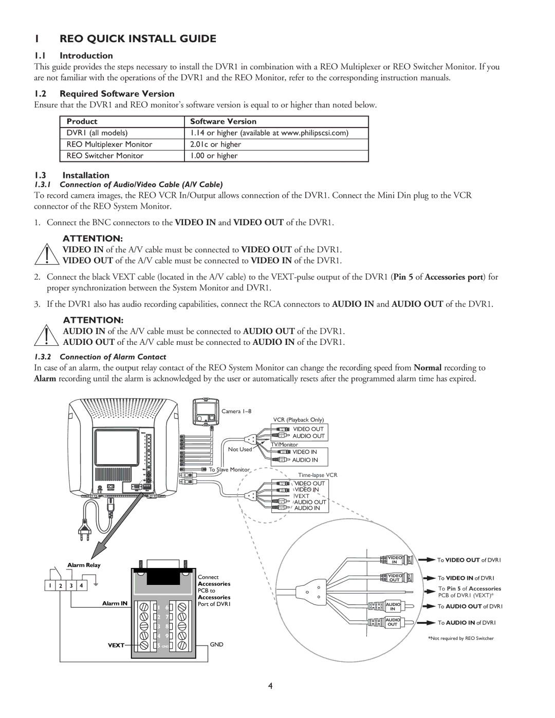
To record camera images, the REO VCR In/Output allows connection of the DVR1. Connect the Mini Din plug to the VCR connector of the REO System Monitor.
1. Connect the BNC connectors to the VIDEO IN and VIDEO OUT of the DVR1.
ATTENTION:
VIDEO IN of the A/V cable must be connected to VIDEO OUT of the DVR1.
VIDEO OUT of the A/V cable must be connected to VIDEO IN of the DVR1.
2.Connect the black VEXT cable (located in the A/V cable) to the
3.If the DVR1 also has audio recording capabilities, connect the RCA connectors to AUDIO IN and AUDIO OUT of the DVR1.
ATTENTION:
AUDIO IN of the A/V cable must be connected to AUDIO OUT of the DVR1.
AUDIO OUT of the A/V cable must be connected to AUDIO IN of the DVR1.
1.3.2Connection of Alarm Contact
In case of an alarm, the output relay contact of the REO System Monitor can change the recording speed from Normal recording to Alarm recording until the alarm is acknowledged by the user or automatically resets after the programmed alarm time has expired.
Camera |
|
|
| VCR (Playback Only) | |
| IN | VIDEO OUT |
| VIDEO |
|
| AUDIO | AUDIO OUT |
| IN | |
Not Used | TV/Monitor | |
VIDEO | VIDEO IN | |
| OUT | |
AUDIO | AUDIO IN |
OUT |
|
To Slave Monitor
| |
| VIDEO OUT |
VIDEO | |
IN | VIDEO IN |
OUT | |
VIDEO | |
VEXT
AUDIO | AUDIO OUT |
IN | |
AUDIO | AUDIO IN |
OUT |
|
| Alarm Relay |
|
|
| |
|
|
|
|
|
| Connect |
1 | 2 | 3 | 4 |
|
| Accessories |
|
| PCB to | ||||
|
|
|
|
|
| |
|
|
| Alarm IN |
|
| Accessories |
|
|
| 1 | 6 | Port of DVR1 | |
|
|
|
|
| ||
|
|
|
| 2 | 7 |
|
|
|
|
| 3 | 8 |
|
|
|
|
| 4 | 9 |
|
|
|
| VEXT | 5 GND | GND | |
VIDEO | To VIDEO OUT of DVR1 | |
IN | ||
VIDEO | To VIDEO IN of DVR1 | |
OUT | ||
| To Pin 5 of Accessories | |
| PCB of DVR1 (VEXT)* | |
AUDIO | To AUDIO OUT of DVR1 | |
IN | ||
| ||
AUDIO | To AUDIO IN of DVR1 | |
OUT | ||
| *Not required by REO Switcher |
4