Installation Procedure
MPC-PSF12/16
Adherence to these instructions will prevent
problems during initial installation of the
The
System | Wiring Harness Used | Color Code |
|
|
|
4 conductor harness | White | |
|
|
|
3 conductor harness | Blue | |
|
|
|
3 conductor harness | Blue | |
|
|
|
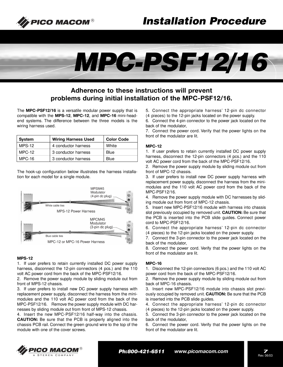
The
MPSM45
Modulator
White cable ties
MPCM45
Modulator
Blue cable ties
MPS-12
1.If user prefers to retain currently installed DC power supply harness, disconnect the
2.Remove the power supply module by sliding module out from front of
3.If user prefers to install new DC power supply harness with replacement power supply, disconnect the harness from the mini- modules and the 110 volt AC power cord from the back of the
4.Insert the new
5.Connect the appropriate harness’
6.Connect the
7.Connect the power cord. Verify that the power lights on the front of the modulator are lit.
MPC-12
1.If user prefers to retain currently installed DC power supply harness, disconnect the
2.Remove the power supply module by sliding module out from front of
3.If user prefers to install new DC power supply harness with replacement power supply, disconnect the harness from the mini- modules and the 110 volt AC power cord from the back of the
4.Remove the power supply module with DC harnesses by slid- ing module out from front of
5.Insert new
6.Connect the appropriate harness’
7.Connect the
8.Connect the power cord. Verify that the power lights on the front of the modulator are lit.
MPC-16
1.Disconnect the
2.Remove the power supply module by sliding module out from back of
3.Insert new
4.Connect the appropriate harness’
5.Connect the
6.Connect the power cord. Verify that the power lights on the front of the modulator are lit.
| 7 | |
|
| Rev. 06/03 |
|
|
|