
A-307R A-209R specifications
The Pioneer A-307R and A-209R are two exceptional integrated amplifiers that showcase Pioneer's commitment to delivering high-quality audio performance for both audiophiles and casual listeners. Renowned for their excellent build quality and advanced technology, these amplifiers serve as a testament to Pioneer's legacy in the audio industry.The A-307R is characterized by its robust design and powerful output capabilities. It boasts a substantial power rating of 100 watts per channel at 8 ohms, making it suitable for a wide range of speakers. This amplifier is engineered with an advanced power amplification system that ensures minimal distortion and a clean, dynamic sound. The A-307R features a high-quality phono stage, allowing users to connect turntables directly, which appeals to vinyl enthusiasts. The inclusion of a low-noise design ensures that the signal remains clean and clear, contributing to an excellent overall listening experience.
On the other hand, the A-209R presents a more compact and budget-friendly option while still maintaining many of the features found in higher-end models. Offering 80 watts per channel, the A-209R is also designed with a solid power amplifier section that provides rich, engaging sound. The simple yet effective user interface allows for easy navigation through various controls, including bass, treble, and balance adjustments, allowing users to tailor the sound to their taste.
Both models incorporate Pioneer's proprietary technologies, such as Direct Energy HD, which enhances audio fidelity by ensuring a direct and unadulterated signal path from the input to the output. This technology minimizes interference and provides a clearer, more detailed soundstage. Additionally, the amplifiers' build quality features a rigid chassis that reduces vibrations, further improving sound clarity.
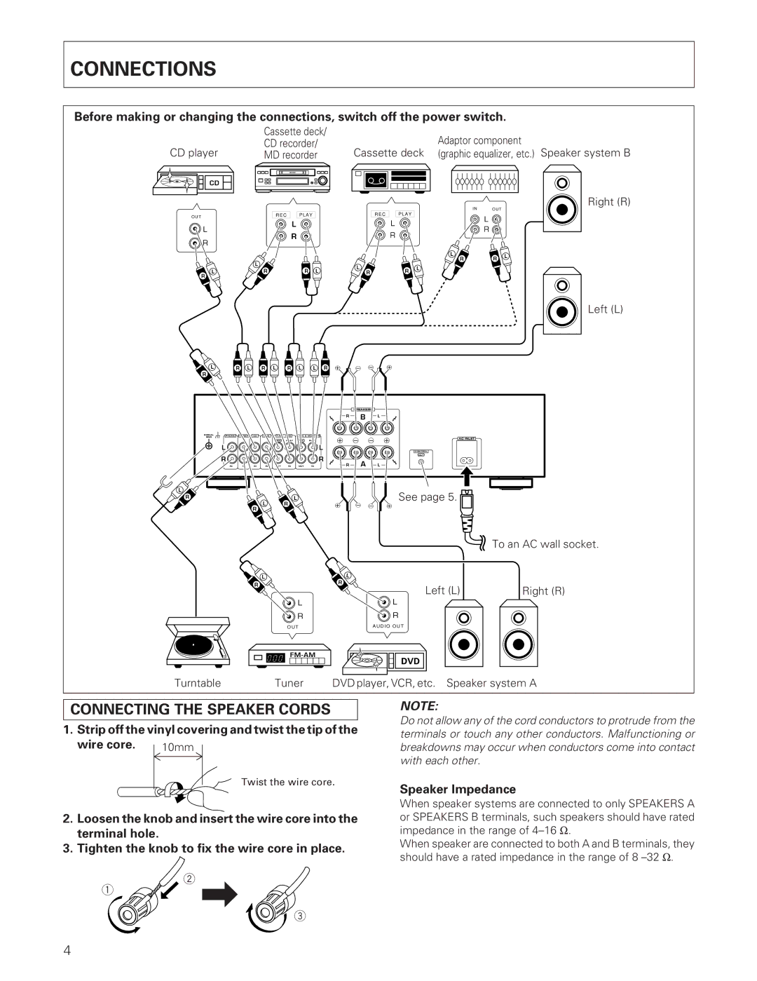
In terms of connectivity, the A-307R and A-209R offer multiple input options, including CD players, tape decks, and auxiliary devices, making them versatile choices for various audio setups. The speaker terminals are robust and can accommodate a range of speaker wire gauges, ensuring secure connections.
Overall, both the Pioneer A-307R and A-209R deliver impressive performance, excellent sound quality, and user-friendly features. With their advanced technologies and solid construction, they represent a reliable choice for anyone looking to enhance their audio experience. Whether for casual listening or critical listening sessions, these amplifiers are sure to satisfy.