Connecting the Unit
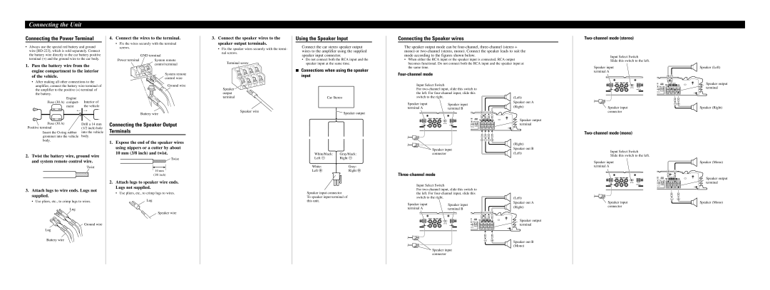
Connecting the Power Terminal
•Always use the special red battery and ground wire
1. Pass the battery wire from the |
engine compartment to the interior |
of the vehicle. |
• After making all other connections to the |
4.Connect the wires to the terminal.
•Fix the wires securely with the terminal screws.
| GND terminal |
Power terminal | System remote |
| control terminal |
| System remote |
| control wire |
3.Connect the speaker wires to the speaker output terminals.
•Fix the speaker wires securely with the termi- nal screws.
Terminal screw
Using the Speaker Input
Connect the car stereo speaker output wires to the amplifier using the supplied speaker input connector.
•Do not connect both the RCA input and the speaker input at the same time.
7Connections when using the speaker input
Connecting the Speaker wires
The speaker output mode can be
•When either the RCA input or the speaker input is connected, RCA output becomes functional. Do not connect both the RCA input and the speaker input at the same time.
Four-channel mode
Two-channel mode (stereo)
Input Select Switch
Slide this switch to the left.
Speaker input terminal A
+ ≠
Speaker (Left)
amplifier, connect the battery wire terminal of |
the amplifier to the positive (+) terminal of |
the battery. |
Engine | Interior of |
Fuse (30 A) compart- | |
ment | the vehicle |
Fuse (30 A) | Drill a 14 mm |
Positive terminal | (1/2 inch) hole |
Insert the | into the vehicle |
grommet into the vehicle | body. |
body. |
|
2.Twist the battery wire, ground wire and system remote control wire.
Twist
Ground wire |
Battery wire
Connecting the Speaker Output Terminals
1.Expose the end of the speaker wires using nippers or a cutter by about 10 mm (3/8 inch) and twist.
![]() Twist
Twist
10 mm
Speaker ![]()
![]() output
output ![]() terminal
terminal
Speaker wire
Car Stereo
![]() Speaker output
Speaker output
White/black: | Gray/black: |
Left ≠ | Right ≠ |
White: | Gray: |
Left + | Right + |
Input Select Switch
For
Speaker input | Speaker input |
terminal A | terminal B |
+ ≠ ≠+
+ ≠ ≠+
Speaker input connector
(Left) Speaker out A (Right)
Speaker output terminal
(Right) Speaker out B (Left)
≠+
Speaker input connector
Two-channel mode (mono)
Input Select Switch
Slide this switch to the left.
Speaker input terminal A
+ | ≠ |
Speaker output terminal
Speaker (Right)
Speaker (Mono)
3.Attach lugs to wire ends. Lugs not supplied.
• Use pliers, etc., to crimp lugs to wires.
Lug
![]() Ground wire
Ground wire
Lug
Battery wire
(3/8 inch)
2.Attach lugs to speaker wire ends. Lugs not supplied.
• Use pliers, etc., to crimp lugs to wires.
Lug
Speaker wire
Speaker input connector
To speaker input terminal of this unit.
Three-channel mode
Input Select Switch
For
Speaker input | Speaker input |
terminal A | terminal B |
+ ≠ ≠+
≠ | + |
Speaker input connector
(Left) Speaker out A (Right)
Speaker output terminal
Speaker out B (Mono)
≠ | + |
Speaker input connector
Speaker output terminal
Speaker (Mono)
