Connecting the Unit
Connecting the Power Terminal
•Always use the special red battery and ground wire
4.Connect the wires to the terminal.
•Fix the wires securely with the terminal screws.
| GND terminal |
Power terminal | System remote |
| control terminal |
Connecting the Speaker Terminals
1.Expose the end of the speaker wires by about 10 mm and twist using nippers or a cutter.
4. Push on the terminal cover.
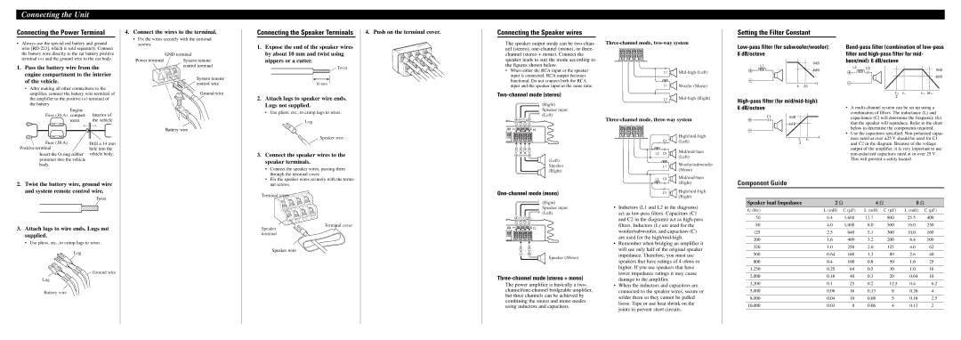
Connecting the Speaker wires
The speaker output mode can be
Setting the Filter Constant
0dB |
L1 |
1. Pass the battery wire from the |
engine compartment to the interior |
of the vehicle. |
• After making all other connections to the |
amplifier, connect the battery wire terminal of |
the amplifier to the positive (+) terminal of |
System remote |
control wire |
Ground wire |
Twist
10 mm
2. Attach lugs to speaker wire ends. |
•When either the RCA input or the speaker input is connected, RCA output becomes functional. Do not connect both the RCA input and the speaker input at the same time.
Two-channel mode (stereo)
C1 ![]()
![]()
L1 ![]() Woofer (Mono)
Woofer (Mono)
f |
fC 2fC |
L2 C2
|
|
| 0dB |
|
|
| |
fCL | fCL | fCH | 2fCH |
2 |
|
|
|
the battery. |
|
|
|
|
|
|
|
| Engine | Interior of | |||||||
Fuse (30 A) compart- | ||||||||||||||||
|
|
|
|
|
|
|
| ment | the vehicle | |||||||
|
|
|
|
|
|
|
|
|
|
|
|
|
|
|
|
|
|
|
|
|
|
|
|
|
|
|
|
|
|
|
|
|
|
|
|
|
|
|
|
|
|
|
|
|
|
|
|
|
|
|
|
|
|
|
|
|
|
|
|
|
|
|
|
|
|
|
|
|
|
|
|
|
|
|
|
|
|
|
|
|
|
|
|
|
|
|
|
|
|
|
|
|
|
|
|
|
|
|
|
|
|
|
|
|
|
|
|
|
|
|
|
|
|
|
|
|
|
|
|
|
|
|
|
|
|
|
|
|
|
|
|
|
|
|
|
Drill a 14 mm hole into the
Insert the
body.
Battery wire
Lugs not supplied. |
• Use pliers, etc., to crimp lugs to wires. |
Lug
Speaker wire
3. Connect the speaker wires to the |
speaker terminals. |
• Connect the speaker wires, passing them |
through the terminal cover. |
![]() (Right) Speaker input (Left)
(Right) Speaker input (Left)
+![]()
![]()
![]()
![]()
![]()
![]()
![]()
![]()
![]()
![]()
(Left) Speaker (Right)
C1
C1 (Left)
|
|
|
|
|
| |
L2 | C2 |
| ||||
|
| (Left) | ||||
|
|
|
|
|
| |
L1 Woofer/subwoofer (Mono)
High-pass filter (for mid/mid-high): 6 dB/octave
C1 | 0dB |
|
|
| |
| fC | f |
| fC | |
| 2 |
|
•A
•Use the capacitors specified.
2.Twist the battery wire, ground wire and system remote control wire.
Twist
3.Attach lugs to wire ends. Lugs not supplied.
• Use pliers, etc., to crimp lugs to wires.
Lug
![]() Ground wire
Ground wire
Lug
Battery wire
• Fix the speaker wires securely with the termi- |
nal screws. |
Terminal screw
Terminal cover
Speaker terminal
Speaker wire
![]() (Right) Speaker input (Left)
(Right) Speaker input (Left)
+![]()
![]()
![]()
![]()
![]()
![]()
![]()
![]()
-+
Speaker (Mono)
Three-channel mode (stereo + mono)
The power amplifier is basically a two-
L2 C2 | |
| (Right) |
C1
•Inductors (L1 and L2 in the diagrams) act as
•Remember when bridging an amplifier it will see only half of the original speaker impedance. Therefore, you must use speakers that have ratings of 4 ohms or higher. If you use speakers that have lower impedance ratings it may cause damage to the amplifier.
•When the inductors and capacitors are connected to the speaker wires, secure or solder them so they cannot be pulled loose. Tape or use heat shrink on the joints to prevent short circuits.
Component Guide
Speaker load Impedance | 2 Ω |
| 4 Ω |
| 8 Ω |
|
fc (Hz) | L (mH) | C (∝F) | L (mH) | C (∝F) | L (mH) | C (∝F) |
|
|
|
|
|
|
|
50 | 6.4 | 1,600 | 12.70 | 800.0 | 25.50 | 400.0 |
|
|
|
|
|
|
|
80 | 4.0 | 1,000 | 8.00 | 500.0 | 16.00 | 250.0 |
|
|
|
|
|
|
|
125 | 2.5 | 640 | 5.10 | 300.0 | 10.00 | 160.0 |
|
|
|
|
|
|
|
200 | 1.6 | 400 | 3.20 | 200.0 | 6.40 | 100.0 |
|
|
|
|
|
|
|
320 | 1.0 | 250 | 2.00 | 125.0 | 4.00 | 62.0 |
|
|
|
|
|
|
|
500 | 0.64 | 160 | 1.30 | 80.0 | 2.60 | 40.0 |
|
|
|
|
|
|
|
800 | 0.4 | 100 | 0.80 | 50.0 | 1.60 | 25.0 |
|
|
|
|
|
|
|
1,250 | 0.25 | 64 | 0.50 | 30.0 | 1.00 | 16.0 |
|
|
|
|
|
|
|
2,000 | 0.16 | 40 | 0.30 | 20.0 | 0.64 | 10.0 |
|
|
|
|
|
|
|
3,200 | 0.1 | 25 | 0.20 | 12.5 | 0.40 | 6.2 |
|
|
|
|
|
|
|
5,000 | 0.06 | 16 | 0.13 | 8.0 | 0.26 | 4.0 |
|
|
|
|
|
|
|
8,000 | 0.04 | 10 | 0.08 | 5.0 | 0.16 | 2.5 |
|
|
|
|
|
|
|
10,000 | 0.03 | 8 | 0.06 | 4.0 | 0.13 | 2.0 |
|
|
|
|
|
|
|