RS232, LAN Command Potocol, PS5580 specifications
The Planar PS4660T and PS5660T series represent a remarkable advancement in touchscreen technology, designed to cater to a variety of applications spanning from retail and transportation to conference rooms and educational settings. Both models offer a vibrant display and a user-friendly interface, setting a new standard for interactive digital signage and information systems.The PS4660T features a 46-inch touchscreen display, while the PS5660T boasts a larger 56-inch display, both providing Full HD resolution for crystal-clear image quality. These screens are designed with advanced LED technology, ensuring bright and vivid colors that enhance visibility even in well-lit environments. The edge-to-edge glass design not only adds to the aesthetic appeal but also offers a robust surface that is resistant to scratches and fingerprints.
One of the standout features of the Planar PS series is its multi-touch capability. The screens support up to 10 simultaneous touch points, enabling multiple users to interact with the display at the same time. This feature is particularly beneficial for collaborative environments and interactive displays in public spaces.
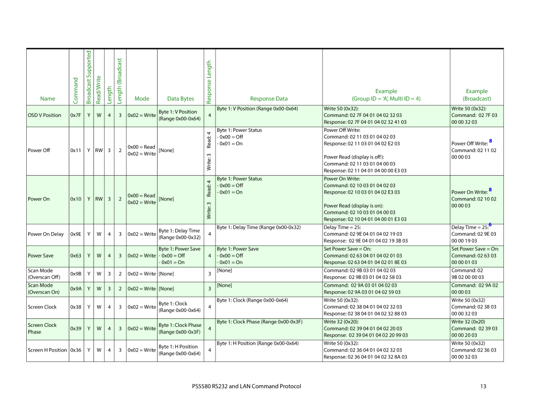
In terms of connectivity, the Planar PS4660T and PS5660T offer versatile options, including HDMI, DisplayPort, and USB. These connections provide easy integration with computers, media players, and other peripherals, making it simple to set up and operate. Additionally, both models feature an RS232 control interface, which allows for device management and integration with third-party control systems, enhancing their versatility in automated environments.
The touchscreens are equipped with advanced optical technology that ensures precise touch recognition, leading to a seamless user experience. This technology also enhances durability, making the units suitable for high-traffic areas where frequent usage is anticipated.
Moreover, Planar's commitment to reliability is evident in the PS series, which includes features such as integrated thermal management and an extended warranty option, ensuring that the displays maintain optimal performance over time.
In conclusion, the Planar PS4660T and PS5660T are innovative touchscreen displays that combine state-of-the-art technology and user-friendly features. With their impressive screen quality, multi-touch capabilities, extensive connectivity options, and reliability, these models are ideal for any interactive application, making them a valuable investment for businesses looking to enhance engagement and interactivity.