APPENDIX A NETWORKING CONNECTION
A.1 Switch‘s RJ-45 Pin Assignments
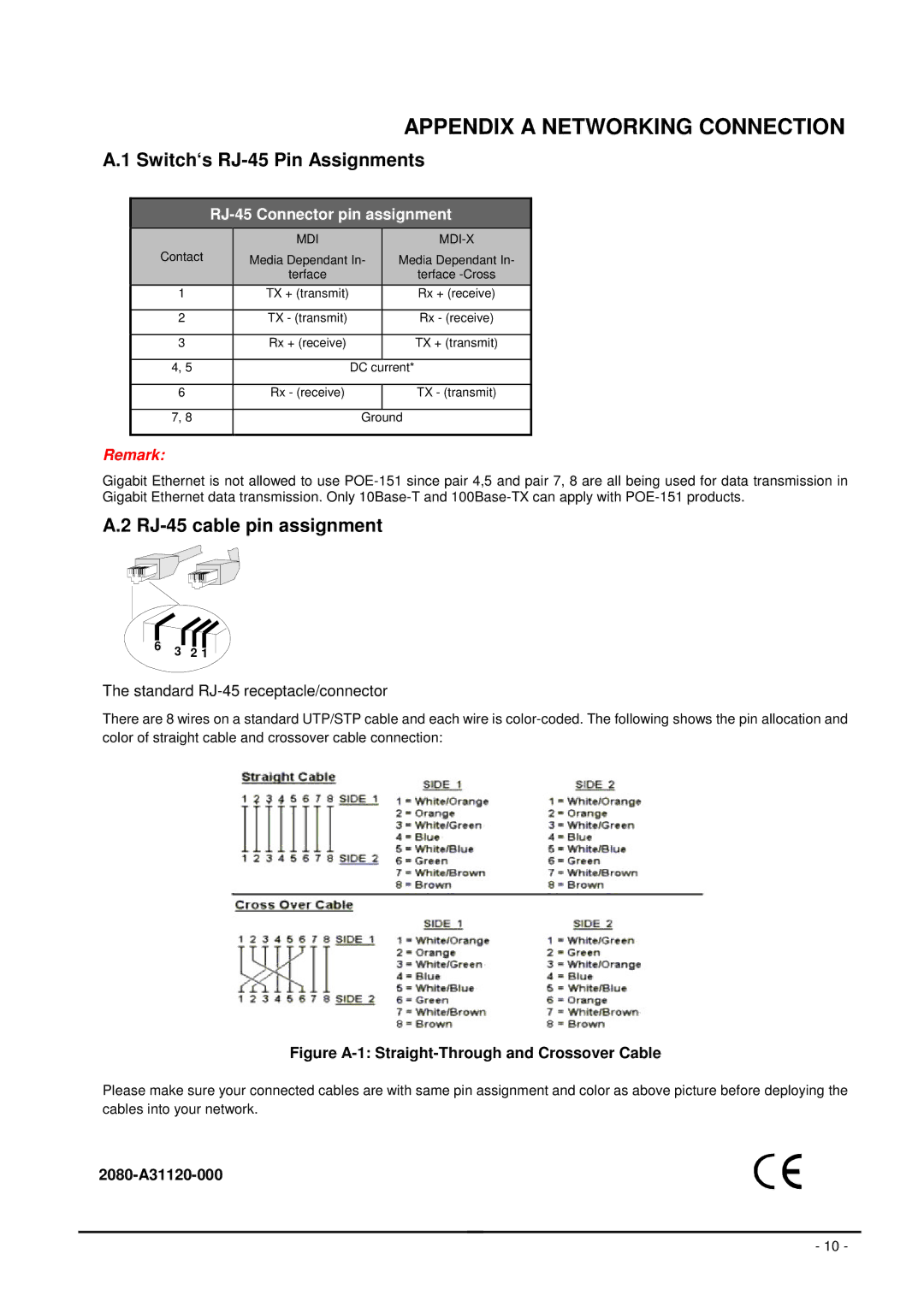
RJ-45 Connector pin assignment
|
| MDI |
|
|
|
| Contact | Media Dependant In- | Media Dependant In- |
| |
|
| terface |
| terface |
|
| 1 | TX + (transmit) |
| Rx + (receive) |
|
|
|
|
|
|
|
| 2 | TX - (transmit) |
| Rx - (receive) |
|
|
|
|
|
|
|
| 3 | Rx + (receive) |
| TX + (transmit) |
|
|
|
|
|
|
|
| 4, 5 |
| DC | current* |
|
|
|
|
|
|
|
| 6 | Rx - (receive) |
| TX - (transmit) |
|
|
|
|
|
|
|
| 7, 8 |
| Ground |
| |
|
|
|
|
|
|
Remark:
Gigabit Ethernet is not allowed to use
A.2 RJ-45 cable pin assignment
6 | 321 |
6 | 321 |
6 3 2 1
The standard RJ-45 receptacle/connector
There are 8 wires on a standard UTP/STP cable and each wire is
Figure A-1: Straight-Through and Crossover Cable
Please make sure your connected cables are with same pin assignment and color as above picture before deploying the cables into your network.
- 10 -