901013 -
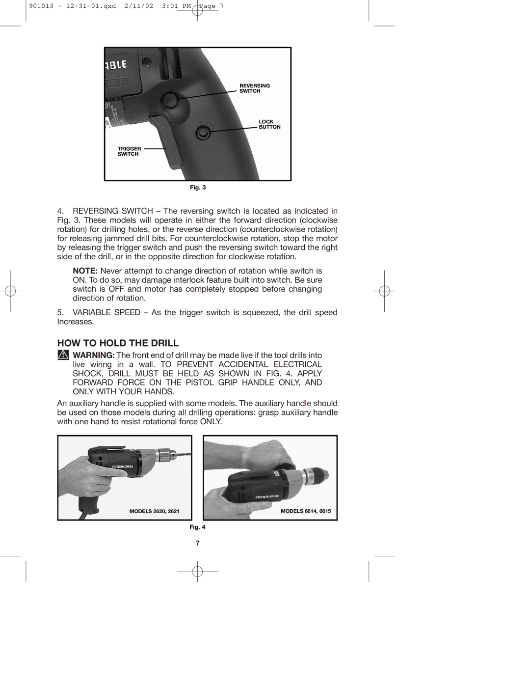
REVERSING
SWITCH
LOCK
BUTTON
TRIGGER
SWITCH
Fig. 3
4.REVERSING SWITCH – The reversing switch is located as indicated in Fig. 3. These models will operate in either the forward direction (clockwise rotation) for drilling holes, or the reverse direction (counterclockwise rotation) for releasing jammed drill bits. For counterclockwise rotation, stop the motor by releasing the trigger switch and push the reversing switch toward the right side of the drill, or in the opposite direction for clockwise rotation.
NOTE: Never attempt to change direction of rotation while switch is ON. To do so, may damage interlock feature built into switch. Be sure switch is OFF and motor has completely stopped before changing direction of rotation.
5.VARIABLE SPEED – As the trigger switch is squeezed, the drill speed Increases.
HOW TO HOLD THE DRILL
![]() WARNING: The front end of drill may be made live if the tool drills into live wiring in a wall. TO PREVENT ACCIDENTAL ELECTRICAL SHOCK, DRILL MUST BE HELD AS SHOWN IN FIG. 4. APPLY FORWARD FORCE ON THE PISTOL GRIP HANDLE ONLY, AND ONLY WITH YOUR HANDS.
WARNING: The front end of drill may be made live if the tool drills into live wiring in a wall. TO PREVENT ACCIDENTAL ELECTRICAL SHOCK, DRILL MUST BE HELD AS SHOWN IN FIG. 4. APPLY FORWARD FORCE ON THE PISTOL GRIP HANDLE ONLY, AND ONLY WITH YOUR HANDS.
An auxiliary handle is supplied with some models. The auxiliary handle should be used on those models during all drilling operations: grasp auxiliary handle with one hand to resist rotational force ONLY.
MODELS 2620, 2621
MODELS 6614, 6615
Fig. 4
7