
DP350 specifications
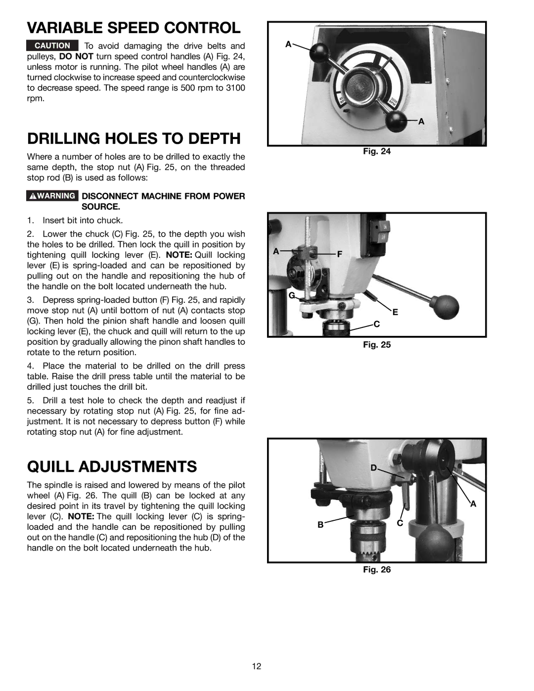
The Porter-Cable DP350 is a versatile and efficient benchtop drill press that stands out in the crowded market of woodworking and metalworking tools. This machine is designed for both DIY enthusiasts and professional tradespeople, making it a reliable choice for a wide range of applications.One of the main features of the Porter-Cable DP350 is its powerful 3.2 amp motor. This robust motor delivers an impressive 3/8-inch chuck capacity, allowing users to drill through a variety of materials, including wood, metal, and plastic. The variable speed settings provide a range from 540 to 3,500 RPM, enabling precise control over drilling operations. This variability is crucial for adapting to different materials and thicknesses, enhancing user capability.
Another standout characteristic is the drill press's 2-inch stroke length, which allows for deeper drilling and increased versatility. This feature is particularly valuable when working with thicker materials or when creating holes that require more depth. The depth stop system is another excellent addition, enabling users to consistently achieve the desired depth across multiple projects.
The DP350 also incorporates a durable and stable base that minimizes vibrations, providing a steady platform for accurate drilling. This stability is complemented by an adjustable work table that can tilt and swivel, allowing for greater flexibility and ease of use. The table can also be easily locked in place, ensuring safety during operation.
Porter-Cable has integrated user-friendly technologies into the DP350 to enhance the overall experience. The quick-release chuck enables rapid bit changes without the need for additional tools, streamlining workflows, especially during frequent bit replacement. The machine is also designed with safety in mind, featuring an on/off switch that allows for quick access in case of emergencies.
For those who prioritize portability, the DP350 remains lightweight, allowing for easy movement without sacrificing power or functionality. This combination of performance and practicality makes it an ideal choice for job site use as well as at-home workshops.
In summary, the Porter-Cable DP350 is a feature-rich drill press that combines power, versatility, and user-friendly technologies. Its robust motor, adjustable features, and safety-focused design make it a top choice for anyone looking to enhance their drilling capabilities, whether for professional projects or hobbyist endeavors.