Manuals
/
Poulan
/
Lawn and Garden
/
Lawn Mower
Poulan
178227
owner manual
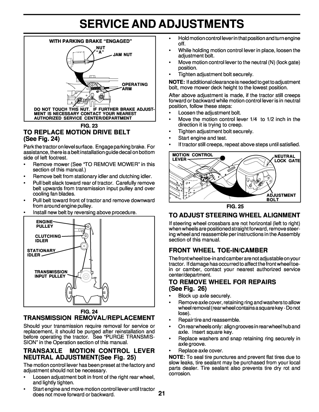
TO REPLACE MOTION DRIVE BELT See Fig, Transmission Removal/Replacement
Models:
178227
1
21
48
48
Download
48 pages
20.12 Kb
18
19
20
21
22
23
24
25
Troubleshooting
Install
Lubrication Chart
Wiring Insulated Clips
Warranty
Assembly
Battery
TO ADJUST GAUGE WHEELS See Fig
Checklist
Clean Air Screen
Page 21
Image 21
Page 20
Page 22
Page 21
Image 21
Page 20
Page 22
Contents
PRK17H42STB
MODEL
IMPORTANT MANUAL Do Not Throw Away
OWNERS MANUAL
Safe Operation Practices for Ride-On Mowers
SAFETY RULES
Look for this symbol to point out im- portant safety precautions. It means CAUTION!!! BECOME ALERT!!! YOUR SAFETY IS INVOLVED
TABLE OF CONTENTS
PRODUCT SPECIFICATIONS
CUSTOMER RESPONSIBILITIES
Steering Wheel
UNASSEMBLED PARTS
Seat
Slope Sheet
TOOLS REQUIRED FOR ASSEMBLY
ASSEMBLY
HOW TO SET UP YOUR TRACTOR
CHECK BATTERY See Fig
INSTALL SEAT See Fig
TO INSTALL MULCHER PLATE See Fig
TO SET UP YOUR MOWER FOR MULCHING
CHECK TIRE PRESSURE
CHECK DECK LEVELNESS
OPERATION
KNOW YOUR TRACTOR
HEIGHT ADJUSTMENT KNOB - Used to adjust the mower cutting height
MOTION CONTROL LEVER Selects the speed and direction of tractor
TO ADJUST MOWER CUTTING HEIGHT See Fig
HOW TO USE YOUR TRACTOR
TO SET PARKING BRAKE See Fig
TO USE THROTTLE CONTROL See Fig
TO OPERATE MOWER See Fig
TO ADJUST GAUGE WHEELS See Fig
TO OPERATE ON HILLS
TO TRANSPORT See Figs. 5 and
CHECK ENGINE OIL LEVEL
BEFORE STARTING THE ENGINE
ADD GASOLINE
TO START ENGINE See Fig
MULCHING MOWING TIPS
MOWING TIPS
MAINTENANCE SCHEDULE
LUBRICATION CHART
CUSTOMER RESPONSIBILITIES
GENERAL RECOMMENDATIONS
TRACTOR
BATTERY
BRAKE OPERATION
TIRES
ENGINE
CLEAN AIR SCREEN
V-BELTS
TRANSAXLE COOLING
CLEANING
CLEAN AIR INTAKE/COOLING AREAS
AIR FILTER See Fig
MUFFLER
TO INSTALL MOWER See Fig
SERVICE AND ADJUSTMENTS
TO LEVEL MOWER HOUSING
TO REMOVE MOWER See Fig
TO ADJUST BRAKE See Fig
TO REPLACE MOWER BLADE DRIVE BELT See Fig
BOTH FRONT LINKS MUST BE EQUAL IN LENGTH
TRANSAXLE MOTION CONTROL LEVER NEUTRAL ADJUSTMENTSee Fig
TRANSMISSION REMOVAL/REPLACEMENT
TO ADJUST STEERING WHEEL ALIGNMENT
TO REPLACE MOTION DRIVE BELT See Fig
REPLACING BATTERY See Figs. 28 and
TO START ENGINE WITH A WEAK BATTERY See Fig
TO REPLACE HEADLIGHT BULB
INTERLOCKS AND RELAYS
TO REMOVE HOOD AND GRILL ASSEMBLY See Fig
TO ADJUST THROTTLE CONTROL CABLE See Fig
TO ADJUST CARBURETOR
OTHER
STORAGE
FUEL SYSTEM
ENGINE OIL
PROBLEM
TROUBLESHOOTING POINTS
CAUSE
CORRECTION
Engine continues to run
TRACTOR - - MODEL NUMBER PRK17H42STB
SCHEMATIC
IGNITION SWITCH
WIRING INSULATED CLIPS
ELECTRICAL
144925
CHASSIS
Screw Hex Wshd 8-18 x 7/8
DRIVE
DRIVE
STEERING ASSEMBLY
175121
KEY PART NO. NO.DESCRIPTION
175146
175118
SEAT ASSEMBLY
WHEELS AND TIRES
DECALS
PART
4,10
OPTIONAL EQUIPMENT Spark Arrester
ENGINE
Washer 5/16 x 3/4 x 16 Ga
MOWER DECK
MOWER DECK
MOWER LIFT
Washer 11/32 x 1-1/2 10 Ga
SERVICE NOTES
SERVICE NOTES
LIMITED WARRANTY
SIGHTING GUIDE
SUGGESTED GUIDE FOR SIGHTING SLOPES FOR SAFE OPERATION
ONLY RIDE UP AND DOWN HILL, NOT ACROSS HILL
SIGHT AND HOLD THIS LEVEL WITH SKY LINE OR TREE 15 MAX
FOR SERVICE OR REPLACEMENT PARTS
PARTS AND SERVICE
Top
Page
Image
Contents