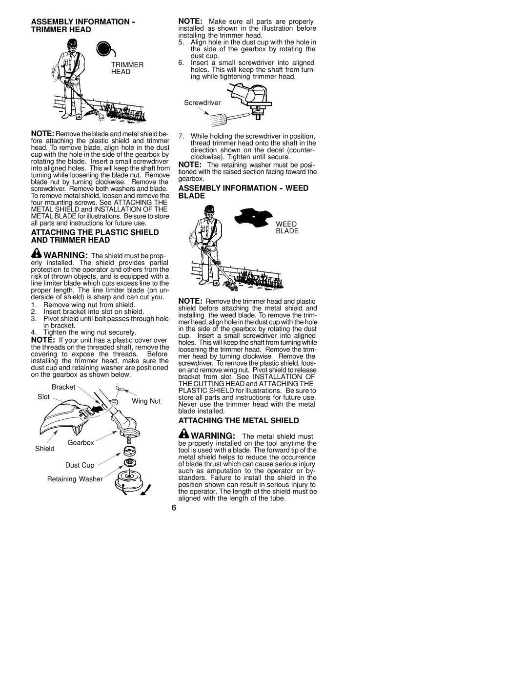
ASSEMBLY INFORMATION - TRIMMER HEAD
TRIMMER
HEAD
NOTE: Make sure all parts are properly installed as shown in the illustration before installing the trimmer head.
5.Align hole in the dust cup with the hole in the side of the gearbox by rotating the dust cup.
6.Insert a small screwdriver into aligned holes. This will keep the shaft from turn- ing while tightening trimmer head.
Screwdriver
NOTE: Remove the blade and metal shield be- fore attaching the plastic shield and trimmer head. To remove blade, align hole in the dust cup with the hole in the side of the gearbox by rotating the blade. Insert a small screwdriver into aligned holes. This will keep the shaft from turning while loosening the blade nut. Remove blade nut by turning clockwise. Remove the screwdriver. Remove both washers and blade. To remove metal shield, loosen and remove the four mounting screws. See ATTACHING THE METAL SHIELD and INSTALLATION OF THE METAL BLADE for illustrations. Be sure to store all parts and instructions for future use.
ATTACHING THE PLASTIC SHIELD AND TRIMMER HEAD
![]() WARNING: The shield must be prop- erly installed. The shield provides partial protection to the operator and others from the risk of thrown objects, and is equipped with a line limiter blade which cuts excess line to the proper length. The line limiter blade (on un- derside of shield) is sharp and can cut you.
WARNING: The shield must be prop- erly installed. The shield provides partial protection to the operator and others from the risk of thrown objects, and is equipped with a line limiter blade which cuts excess line to the proper length. The line limiter blade (on un- derside of shield) is sharp and can cut you.
1.Remove wing nut from shield.
2.Insert bracket into slot on shield.
3.Pivot shield until bolt passes through hole in bracket.
4.Tighten the wing nut securely.
NOTE: If your unit has a plastic cover over the threads on the threaded shaft, remove the covering to expose the threads. Before installing the trimmer head, make sure the dust cup and retaining washer are positioned on the gearbox as shown below.
| Bracket |
Slot | Wing Nut |
|
7.While holding the screwdriver in position, thread trimmer head onto the shaft in the direction shown on the decal (counter- clockwise). Tighten until secure.
NOTE: The retaining washer must be posi- tioned with the raised section facing toward the gearbox.
ASSEMBLY INFORMATION - WEED BLADE
WEED
BLADE
NOTE: Remove the trimmer head and plastic shield before attaching the metal shield and installing the weed blade. To remove the trim- mer head, align hole in the dust cup with the hole in the side of the gearbox by rotating the dust cup. Insert a small screwdriver into aligned holes. This will keep the shaft from turning while loosening the trimmer head. Remove the trim- mer head by turning clockwise. Remove the screwdriver. To remove the plastic shield, loos- en and remove wing nut. Pivot shield to release bracket from slot. See INSTALLATION OF THE CUTTING HEAD and ATTACHING THE PLASTIC SHIELD for illustrations. Be sure to store all parts and instructions for future use. Never use the trimmer head with the metal blade installed.
ATTACHING THE METAL SHIELD
Shield
Gearbox ![]()
![]()
![]() WARNING: The metal shield must be properly installed on the tool anytime the tool is used with a blade. The forward tip of the
WARNING: The metal shield must be properly installed on the tool anytime the tool is used with a blade. The forward tip of the
Dust Cup
Retaining Washer
metal shield helps to reduce the occurrence of blade thrust which can cause serious injury such as amputation to the operator or by- standers. Failure to install the shield in the position shown can result in serious injury to the operator. The length of the shield must be aligned with the length of the tube.
6