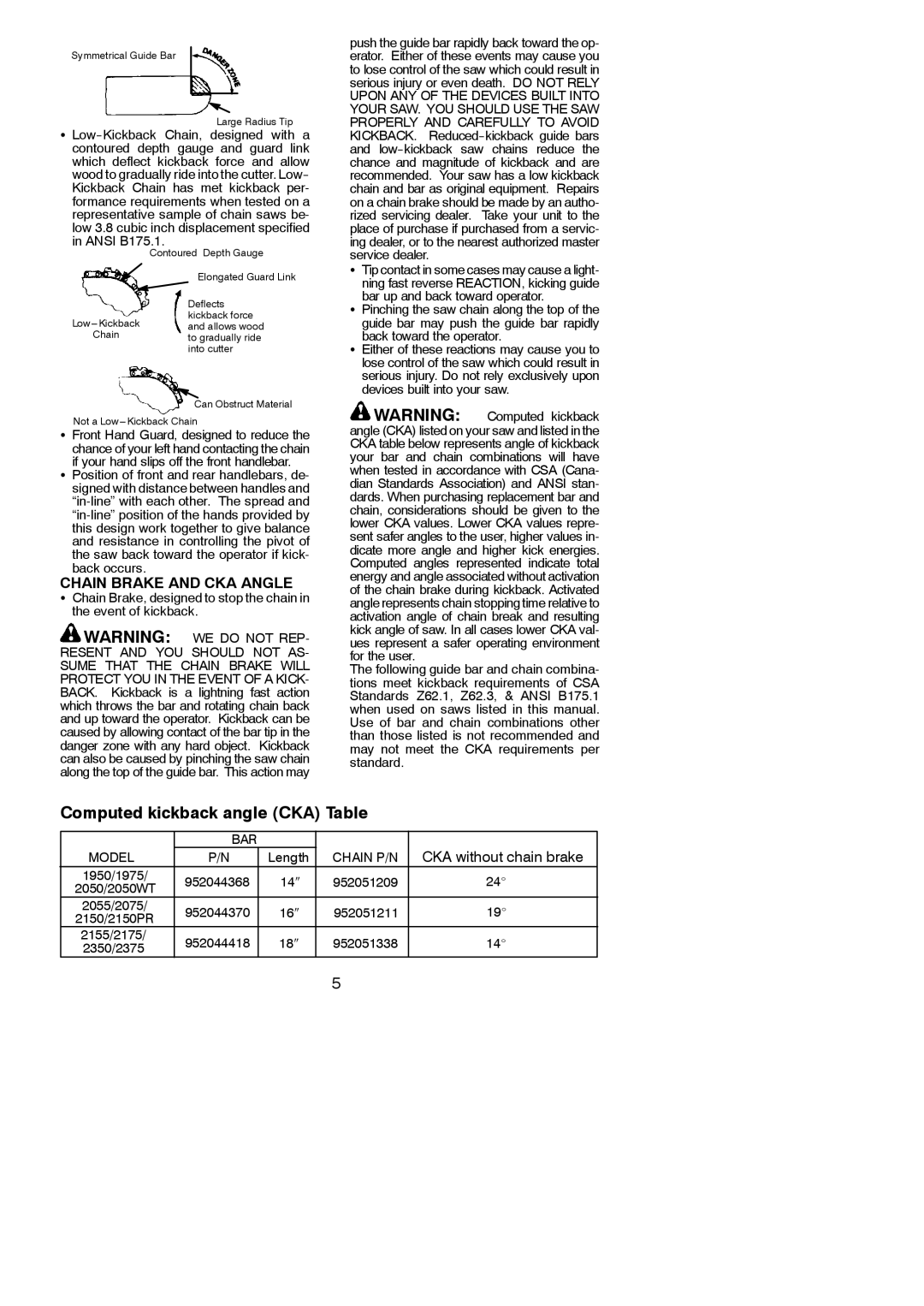
Symmetrical Guide Bar
Large Radius Tip
S
Contoured Depth Gauge
| Elongated Guard Link | |
| Deflects | |
kickback force | ||
and allows wood | ||
Chain | ||
to gradually ride | ||
| into cutter | |
| Can Obstruct Material |
Not a
SFront Hand Guard, designed to reduce the
chance of your left hand contacting the chain if your hand slips off the front handlebar.
SPosition of front and rear handlebars, de- signed with distance between handles and
CHAIN BRAKE AND CKA ANGLE
SChain Brake, designed to stop the chain in the event of kickback.
![]() WARNING: WE DO NOT REP- RESENT AND YOU SHOULD NOT AS- SUME THAT THE CHAIN BRAKE WILL PROTECT YOU IN THE EVENT OF A KICK- BACK. Kickback is a lightning fast action which throws the bar and rotating chain back and up toward the operator. Kickback can be caused by allowing contact of the bar tip in the danger zone with any hard object. Kickback can also be caused by pinching the saw chain along the top of the guide bar. This action may
WARNING: WE DO NOT REP- RESENT AND YOU SHOULD NOT AS- SUME THAT THE CHAIN BRAKE WILL PROTECT YOU IN THE EVENT OF A KICK- BACK. Kickback is a lightning fast action which throws the bar and rotating chain back and up toward the operator. Kickback can be caused by allowing contact of the bar tip in the danger zone with any hard object. Kickback can also be caused by pinching the saw chain along the top of the guide bar. This action may
push the guide bar rapidly back toward the op- erator. Either of these events may cause you to lose control of the saw which could result in serious injury or even death. DO NOT RELY UPON ANY OF THE DEVICES BUILT INTO YOUR SAW. YOU SHOULD USE THE SAW PROPERLY AND CAREFULLY TO AVOID KICKBACK.
STip contact in some cases may cause a light- ning fast reverse REACTION, kicking guide bar up and back toward operator.
SPinching the saw chain along the top of the
guide bar may push the guide bar rapidly back toward the operator.
SEither of these reactions may cause you to lose control of the saw which could result in serious injury. Do not rely exclusively upon devices built into your saw.
![]() WARNING: Computed kickback angle (CKA) listed on your saw and listed in the CKA table below represents angle of kickback your bar and chain combinations will have when tested in accordance with CSA (Cana- dian Standards Association) and ANSI stan- dards. When purchasing replacement bar and chain, considerations should be given to the lower CKA values. Lower CKA values repre- sent safer angles to the user, higher values in- dicate more angle and higher kick energies. Computed angles represented indicate total energy and angle associated without activation of the chain brake during kickback. Activated angle represents chain stopping time relative to activation angle of chain break and resulting kick angle of saw. In all cases lower CKA val- ues represent a safer operating environment for the user.
WARNING: Computed kickback angle (CKA) listed on your saw and listed in the CKA table below represents angle of kickback your bar and chain combinations will have when tested in accordance with CSA (Cana- dian Standards Association) and ANSI stan- dards. When purchasing replacement bar and chain, considerations should be given to the lower CKA values. Lower CKA values repre- sent safer angles to the user, higher values in- dicate more angle and higher kick energies. Computed angles represented indicate total energy and angle associated without activation of the chain brake during kickback. Activated angle represents chain stopping time relative to activation angle of chain break and resulting kick angle of saw. In all cases lower CKA val- ues represent a safer operating environment for the user.
The following guide bar and chain combina- tions meet kickback requirements of CSA Standards Z62.1, Z62.3, & ANSI B175.1 when used on saws listed in this manual. Use of bar and chain combinations other than those listed is not recommended and may not meet the CKA requirements per standard.
Computed kickback angle (CKA) Table
| MODEL | BAR |
|
| CKA without chain brake | |
| P/N | Length | CHAIN P/N | |||
1950/1975/ | 952044368 | 14″ | 952051209 | 24_ | ||
| 2050/2050WT | |||||
|
|
|
|
| ||
2055/2075/ | 952044370 | 16″ | 952051211 | 19_ | ||
| 2150/2150PR | |||||
|
|
|
|
| ||
| 2155/2175/ | 952044418 | 18″ | 952051338 | 14_ | |
2350/2375 | ||||||
|
|
|
| |||
5
