2. Press and hold the locking/release button.
Locking/Release
Button
Attachment | Coupler | Upper Shaft |
3.While securely holding the engine and upper shaft, pull the attachment straight out of the coupler.
INSTALLING OPTIONAL ATTACH- MENTS
1.Remove the shaft cap from the attach- ment (if present).
2.Position locking/release button of attach- ment into guide recess of coupler.
3.Push the attachment into the coupler until the locking/release button snaps into the primary hole.
4.Before using the unit, tighten the knob se- curely by turning clockwise.
Coupler Primary Hole
Guide Recess
Locking/
Upper Release Attachment
Shaft Button
![]() WARNING: Make sure the locking/ release button is locked in the primary hole and the knob is securely tightened before op- erating the unit. All attachments are designed to be used in the primary hole unless otherwise stated in the applicable attachment instruction manual. Using the wrong hole could lead to seri- ous injury or damage to the unit.
WARNING: Make sure the locking/ release button is locked in the primary hole and the knob is securely tightened before op- erating the unit. All attachments are designed to be used in the primary hole unless otherwise stated in the applicable attachment instruction manual. Using the wrong hole could lead to seri- ous injury or damage to the unit.
Locking/Release
Button in Primary Hole
OPERATING INSTRUCTIONS
It is recommended that the engine not be operated for longer than 1 minute at full throttle.
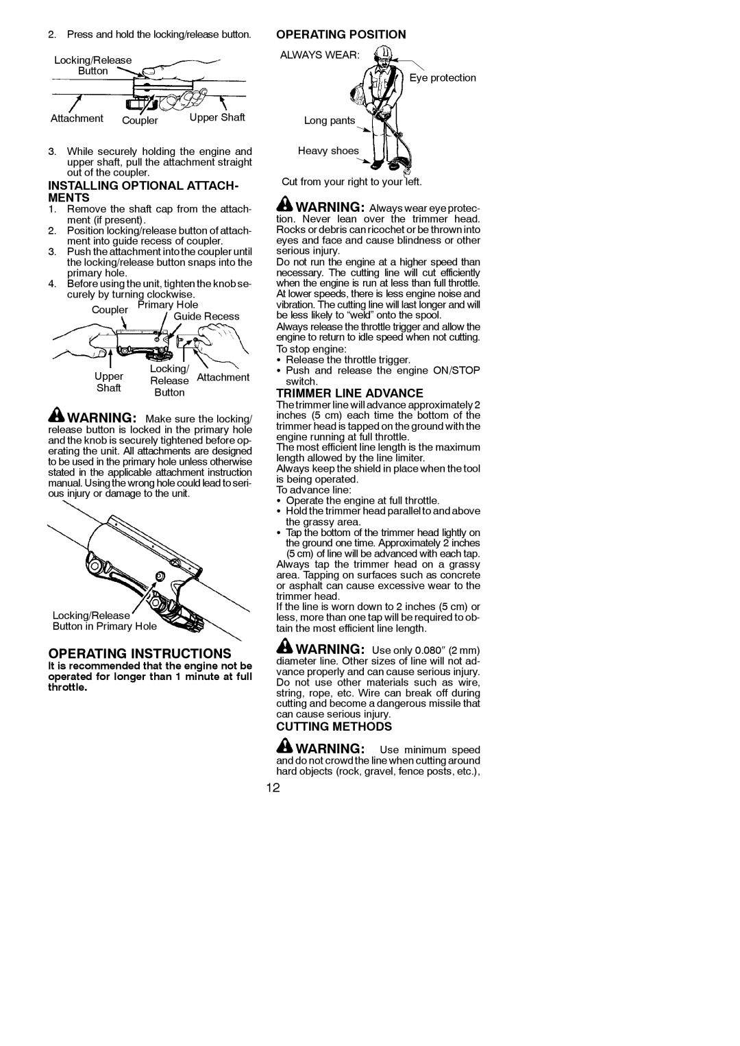
OPERATING POSITION
ALWAYS WEAR:
Eye protection
Long pants
Heavy shoes
Cut from your right to your left.
![]() WARNING: Always wear eye protec- tion. Never lean over the trimmer head. Rocks or debris can ricochet or be thrown into eyes and face and cause blindness or other serious injury.
WARNING: Always wear eye protec- tion. Never lean over the trimmer head. Rocks or debris can ricochet or be thrown into eyes and face and cause blindness or other serious injury.
Do not run the engine at a higher speed than necessary. The cutting line will cut efficiently when the engine is run at less than full throttle. At lower speeds, there is less engine noise and vibration. The cutting line will last longer and will be less likely to “weld” onto the spool.
Always release the throttle trigger and allow the engine to return to idle speed when not cutting. To stop engine:
SRelease the throttle trigger.
S Push and release the engine ON/STOP switch.
TRIMMER LINE ADVANCE
The trimmer line will advance approximately 2 inches (5 cm) each time the bottom of the trimmer head is tapped on the ground with the engine running at full throttle.
The most efficient line length is the maximum length allowed by the line limiter.
Always keep the shield in place when the tool is being operated.
To advance line:
SOperate the engine at full throttle.
SHold the trimmer head parallel to and above
the grassy area.
STap the bottom of the trimmer head lightly on the ground one time. Approximately 2 inches
(5 cm) of line will be advanced with each tap. Always tap the trimmer head on a grassy area. Tapping on surfaces such as concrete or asphalt can cause excessive wear to the trimmer head.
If the line is worn down to 2 inches (5 cm) or less, more than one tap will be required to ob- tain the most efficient line length.
![]() WARNING: Use only 0.080″ (2 mm) diameter line. Other sizes of line will not ad- vance properly and can cause serious injury. Do not use other materials such as wire, string, rope, etc. Wire can break off during cutting and become a dangerous missile that can cause serious injury.
WARNING: Use only 0.080″ (2 mm) diameter line. Other sizes of line will not ad- vance properly and can cause serious injury. Do not use other materials such as wire, string, rope, etc. Wire can break off during cutting and become a dangerous missile that can cause serious injury.
CUTTING METHODS
![]() WARNING: Use minimum speed and do not crowd the line when cutting around hard objects (rock, gravel, fence posts, etc.),
WARNING: Use minimum speed and do not crowd the line when cutting around hard objects (rock, gravel, fence posts, etc.),
12