ASSEMBLY
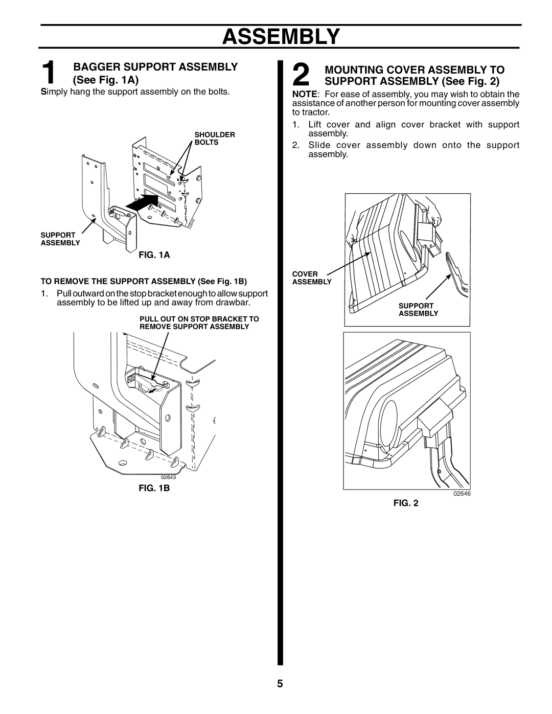
1 | BAGGER SUPPORT ASSEMBLY |
(See Fig. 1A) |
Simply hang the support assembly on the bolts.
SHOULDER
BOLTS
SUPPORT
ASSEMBLY
FIG. 1A
TO REMOVE THE SUPPORT ASSEMBLY (See Fig. 1B)
1.Pull outward on the stop bracket enough to allow support assembly to be lifted up and away from drawbar.
PULL OUT ON STOP BRACKET TO
REMOVE SUPPORT ASSEMBLY
02643
FIG. 1B
2 | MOUNTING COVER ASSEMBLY TO |
SUPPORT ASSEMBLY (See Fig. 2) |
NOTE: For ease of assembly, you may wish to obtain the assistance of another person for mounting cover assembly to tractor.
1.Lift cover and align cover bracket with support assembly.
2.Slide cover assembly down onto the support assembly.
COVER
ASSEMBLY
SUPPORT |
ASSEMBLY |
02646 |
FIG. 2
5