OPERATION
TO ADJUST GAUGE WHEELS (See Fig. 7)
Gauge wheels are properly adjusted when they are slightly off the ground when mower is at the desired cutting height in operating position. Gauge wheels then keep the deck in proper position to help prevent scalping in most terrain conditions.
NOTE:Adjust gauge wheels with tractor on a flat level surface.
•Adjust mower to desired cutting height (See “TO AD- JUST MOWER CUTTING HEIGHT” in the Operation section of this manual).
•Remove retainer spring and clevis pin which secure each gauge wheel bar.
•Lower gauge wheels to ground. Raise gauge wheels slightly to align holes in bracket and gauge wheel bar and insert clevis pin. Gauge wheels should be slightly off the ground.
•Replace retainer spring into clevis pin.
•Be sure all gauge wheels are in the same setting.
IMPORTANT:BE SURETO READJUST GAUGEWHEELS IFYOU CHANGE THE CUTTING HEIGHT OF THE MOWER DECK.
RETAINER
SPRING
CLEVIS
PIN
FIG. 7
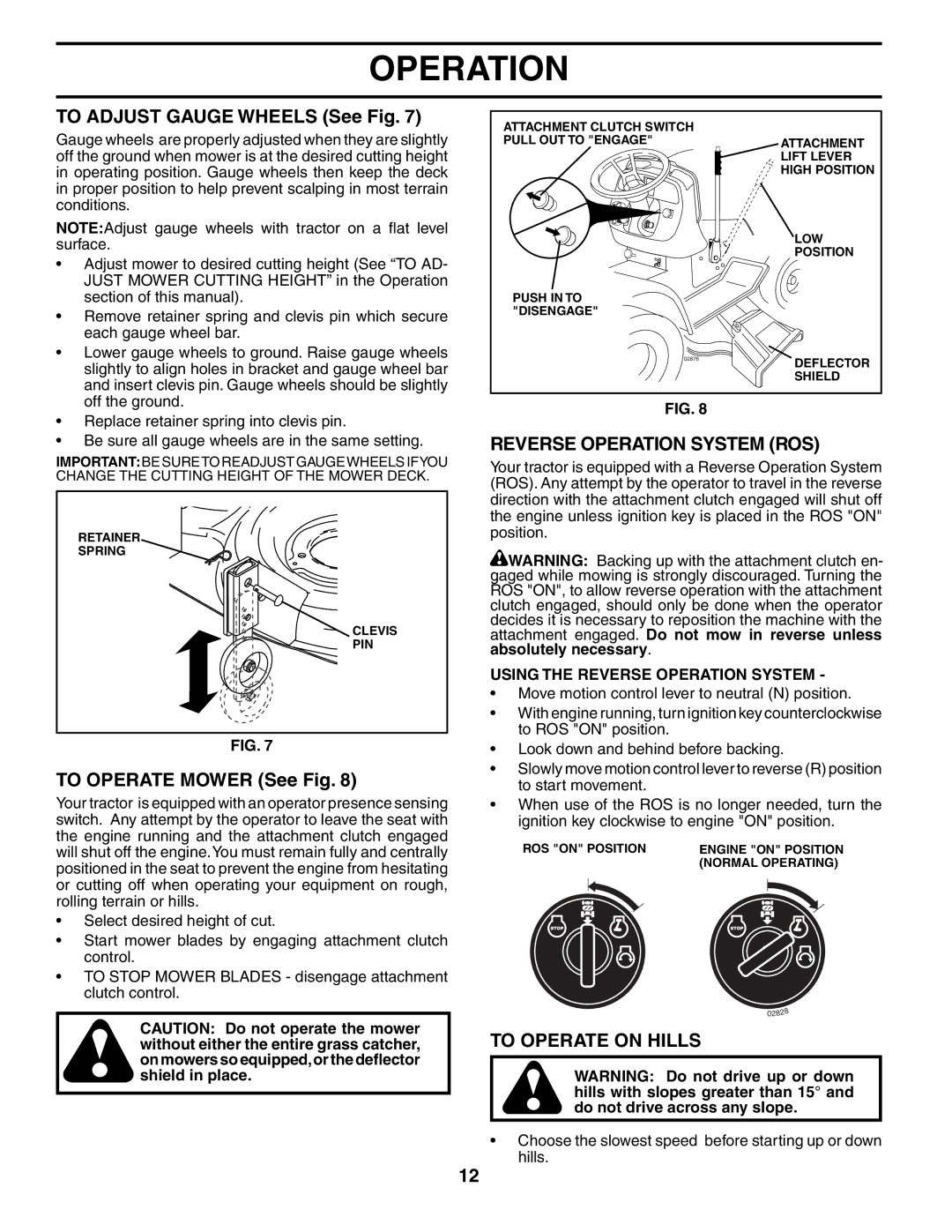
TO OPERATE MOWER (See Fig. 8)
Your tractor is equipped with an operator presence sensing switch. Any attempt by the operator to leave the seat with the engine running and the attachment clutch engaged will shut off the engine.You must remain fully and centrally positioned in the seat to prevent the engine from hesitating or cutting off when operating your equipment on rough, rolling terrain or hills.
•Select desired height of cut.
•Start mower blades by engaging attachment clutch control.
•TO STOP MOWER BLADES - disengage attachment clutch control.
CAUTION: Do not operate the mower without either the entire grass catcher, on mowers so equipped,or the deflector shield in place.
ATTACHMENT CLUTCH SWITCH
PULL OUT TO "ENGAGE"ATTACHMENT LIFT LEVER HIGH POSITION
LOW
POSITION
PUSH IN TO "DISENGAGE"
02876DEFLECTOR
SHIELD
FIG. 8
REVERSE OPERATION SYSTEM (ROS)
Your tractor is equipped with a Reverse Operation System (ROS). Any attempt by the operator to travel in the reverse direction with the attachment clutch engaged will shut off the engine unless ignition key is placed in the ROS "ON" position.
![]() WARNING: Backing up with the attachment clutch en- gaged while mowing is strongly discouraged. Turning the ROS "ON", to allow reverse operation with the attachment clutch engaged, should only be done when the operator decides it is necessary to reposition the machine with the attachment engaged. Do not mow in reverse unless absolutely necessary.
WARNING: Backing up with the attachment clutch en- gaged while mowing is strongly discouraged. Turning the ROS "ON", to allow reverse operation with the attachment clutch engaged, should only be done when the operator decides it is necessary to reposition the machine with the attachment engaged. Do not mow in reverse unless absolutely necessary.
USING THE REVERSE OPERATION SYSTEM -
•Move motion control lever to neutral (N) position.
•With engine running, turn ignition key counterclockwise to ROS "ON" position.
•Look down and behind before backing.
•Slowly move motion control lever to reverse (R) position to start movement.
•When use of the ROS is no longer needed, turn the ignition key clockwise to engine "ON" position.
ROS "ON" POSITION | ENGINE "ON" POSITION |
| (NORMAL OPERATING) |
02828
TO OPERATE ON HILLS
WARNING: Do not drive up or down hills with slopes greater than 15° and do not drive across any slope.
•Choose the slowest speed before starting up or down hills.
12