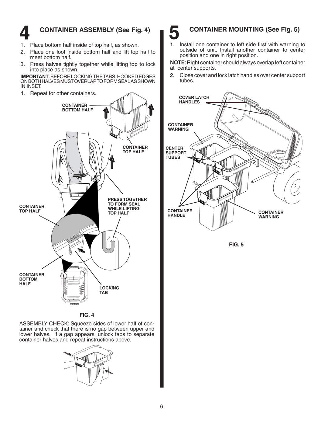
4 CONTAINER ASSEMBLY (See Fig. 4)
1.Place bottom half inside of top half, as shown.
2.Place one foot inside bottom half and lift top half to meet bottom half.
3.Press halves tightly together while lifting top to lock into place as shown.
IMPORTANT:BEFORE LOCKINGTHETABS, HOOKED EDGES ON BOTH HALVES MUST OVERLAPTO FORM SEAL AS SHOWN IN INSET.
4. Repeat for other containers.
CONTAINER
BOTTOM HALF
02089
CONTAINER
TOP HALF
| 39 | |
| 027 | |
| PRESS TOGETHER | |
CONTAINER | TO FORM SEAL | |
WHILE LIFTING | ||
TOP HALF | ||
TOP HALF | ||
|
5 CONTAINER MOUNTING (See Fig. 5)
1.Install one container to left side first with warning to outside of unit. Install another container to center position and one in right position.
NOTE: Right container should always overlap left container at center supports.
2.Close cover and lock latch handles over center support tubes.
COVER LATCH
HANDLES
CONTAINER
WARNING
CENTER
SUPPORT
TUBES
|
| WAR | NING |
|
|
| |
03022 |
|
|
|
| WAR | NING |
|
|
|
| |
CONTAINER |
|
| CONTAINER |
HANDLE |
|
| |
|
| WARNING | |
|
|
|
CONTAINER
BOTTOM
HALF
LOCKING
TAB
FIG. 4
ASSEMBLY CHECK: Squeeze sides of lower half of con- tainer and check that there is no gap between upper and lower halves. If a gap appears, unlock tabs to separate container halves and repeat instructions above.
02097
FIG. 5
6