SERVICE AND ADJUSTMENTS
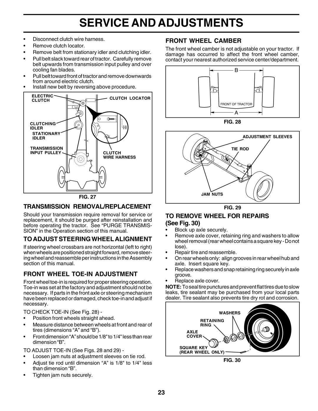
•Disconnect clutch wire harness.
•Remove clutch locator.
•Remove belt from stationary idler and clutching idler.
•Pull belt slack toward rear of tractor. Carefully remove belt upwards from transmission input pulley and over cooling fan blades.
•Pull belt toward front of tractor and remove downwards from around electric clutch.
•Install new belt by reversing above procedure.
ELECTRIC | CLUTCH LOCATOR | |
CLUTCH | ||
|
CLUTCHING
IDLER
STATIONARY
IDLER
TRANSMISSION
INPUT PULLEYCLUTCH WIRE HARNESS
FIG. 27
TRANSMISSION REMOVAL/REPLACEMENT
Should your transmission require removal for service or replacement, it should be purged after reinstallation and before operating the tractor. See “PURGE TRANSMIS- SION” in the Operation section of this manual.
TO ADJUST STEERING WHEEL ALIGNMENT
If steering wheel crossbars are not horizontal (left to right) when wheels are positioned straight forward, remove steer- ing wheel and reassemble per instructions in the Assembly section of this manual.
FRONT WHEEL TOE-IN ADJUSTMENT
Front wheel
TO CHECK
•Position front wheels straight ahead.
•Measure distance between wheels at front and rear of tires (dimensions “A” and “B”).
•Front dimension “A” should be 1/8" to 1/4" less than rear dimension “B”.
TO ADJUST
•Loosen jam nuts at adjustment sleeves on tie rod.
•Adjust tie rod until dimension “A” is 1/8" to 1/4" less than dimension “B”.
•Tighten jam nuts securely.
FRONT WHEEL CAMBER
The front wheel camber is not adjustable on your tractor. If damage has occurred to affect the front wheel camber, contact your nearest authorized service center/department.
![]() B
B ![]()
FRONT OF TRACTOR
![]() A
A ![]()
FIG. 28
ADJUSTMENT SLEEVES
TIE ROD
JAM NUTS
FIG. 29
TO REMOVE WHEEL FOR REPAIRS (See Fig. 30)
•Block up axle securely.
•Remove axle cover, retaining ring and washers to allow wheel removal (rear wheel contains a square key - Do not lose).
•Repair tire and reassemble.
•On rear wheels only: align grooves in rear wheel hub and axle. Insert square key.
•Replace washers and snap retaining ring securely in axle groove.
•Replace axle cover.
NOTE: To seal tire punctures and prevent flat tires due to slow leaks, tire sealant may be purchased from your local parts dealer. Tire sealant also prevents tire dry rot and corrosion.
WASHERS
RETAINING
RING
AXLE
COVER ![]()
SQUARE KEY
(REAR WHEEL ONLY) ![]()
FIG. 30
23