ASSEMBLY
1 | BAGGER SUPPORT ASSEMBLY |
| (See Figs. 1A & 1B) |
1.Remove and discard the upper bolt on both sides of the drawbar. Using the same holes, install the shoulder bolts supplied and tighten securely.
REMOVE AND DISCARD
UPPER BOLTS AND INSTALL
SHOULDER BOLTS SUPPLIED
| 253 | 1 |
0 |
| |
|
|
DRAWBAR
FIG. 1A
2.Align support assembly pin with hole in drawbar and hang assembly over the shoulder bolts.
3.Be sure support assembly is seated properly and secure with retainer spring supplied.
SHOULDER
BOLTS
SUPPORT
ASSEMBLY
SPRING | 02530 |
RETAINER |
|
PIN
FIG. 1B
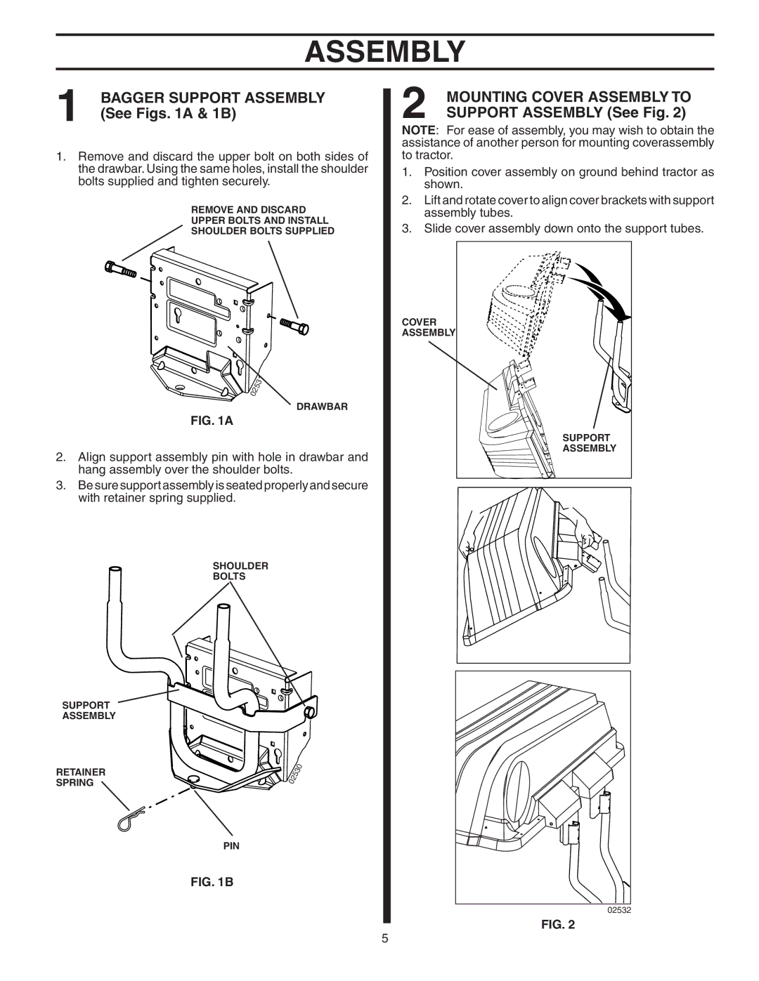
2 | MOUNTING COVER ASSEMBLY TO |
SUPPORT ASSEMBLY (See Fig. 2) |
NOTE: For ease of assembly, you may wish to obtain the assistance of another person for mounting coverassembly to tractor.
1.Position cover assembly on ground behind tractor as shown.
2.Lift and rotate cover to align cover brackets with support assembly tubes.
3.Slide cover assembly down onto the support tubes.
COVER
ASSEMBLY
SUPPORT
ASSEMBLY
02532 |
FIG. 2
5