SERVICE AND ADJUSTMENTS
PRECISION
•With all tires properly inflated, park tractor on level ground or driveway.
CAUTION: Blades are sharp. Protect your hands with gloves and/or wrap blade with heavy cloth.
•Raise mower to its highest position.
•At both sides of mower, position blade at side and measure the distance (A) from bottom edge of blade to the ground. The distance should be the same on both sides.
•If adjustment is necessary, see steps in Visual Adjust- ment instructions above.
•Recheck measurements, adjust if necessary until both sides are equal.
| 02966 |
A | A |
FIG. 24
To obtain the best cutting results, the mower blades should be adjusted so the front tip is 1/8" to 1/2" lower than the rear tip when the mower is in its highest position.
CAUTION: Blades are sharp. Protect your hands with gloves and/or wrap blade with heavy cloth.
•Raise mower to highest position.
•Position any blade so the tip is pointing straight forward. Measure distance (B) to the ground at front and rear tip of the blade.
•If front tip of blade is not 1/8" to 1/2" lower than the rear tip, go to the front of tractor.
•With an 11/16" or adjustable wrench, loosen jam nut A several turns to clear adjustment nut B.
•With a 3/4" or adjustable wrench, turn front link adjust- ment nut (B) clockwise (ltighten) to raise the front of mower, or, counterclockwise (loosen) to lower the front mower.
02548
BB
FIG. 25
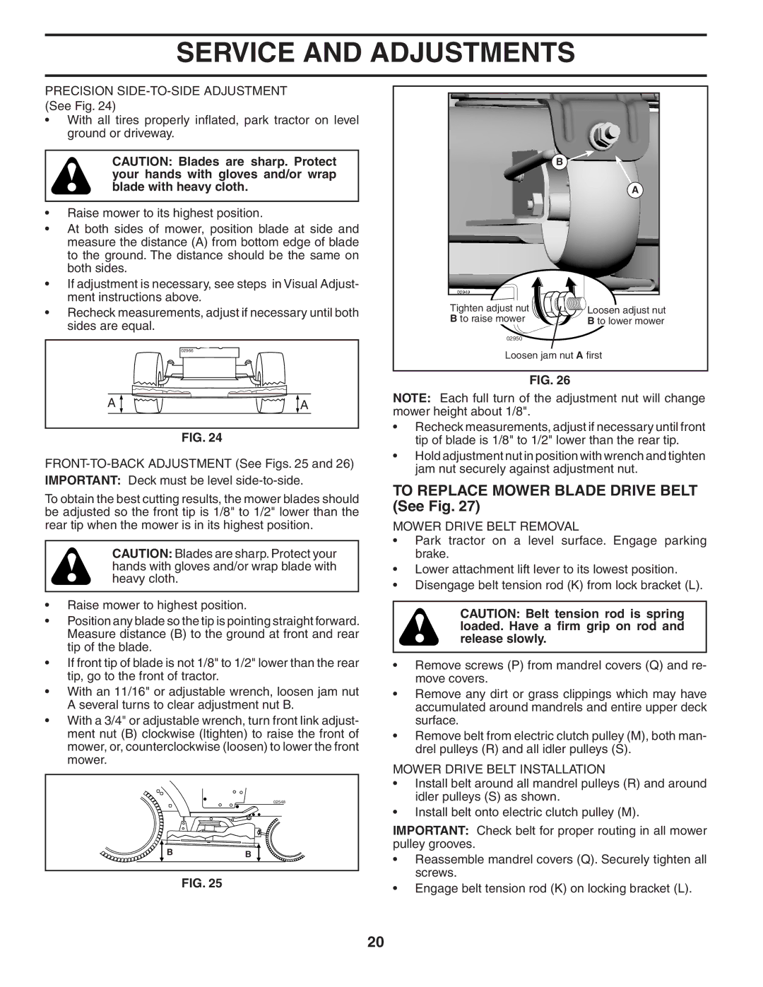
B
A
Tighten adjust nut | Loosen adjust nut |
B to raise mower | B to lower mower |
02950
Loosen jam nut A first
FIG. 26
NOTE: Each full turn of the adjustment nut will change mower height about 1/8".
•Recheck measurements, adjust if necessary until front tip of blade is 1/8" to 1/2" lower than the rear tip.
•Hold adjustment nut in position with wrench and tighten jam nut securely against adjustment nut.
TO REPLACE MOWER BLADE DRIVE BELT (See Fig. 27)
MOWER DRIVE BELT REMOVAL
•Park tractor on a level surface. Engage parking brake.
•Lower attachment lift lever to its lowest position.
•Disengage belt tension rod (K) from lock bracket (L).
CAUTION: Belt tension rod is spring loaded. Have a firm grip on rod and release slowly.
•Remove screws (P) from mandrel covers (Q) and re- move covers.
•Remove any dirt or grass clippings which may have accumulated around mandrels and entire upper deck surface.
•Remove belt from electric clutch pulley (M), both man- drel pulleys (R) and all idler pulleys (S).
MOWER DRIVE BELT INSTALLATION
•Install belt around all mandrel pulleys (R) and around idler pulleys (S) as shown.
•Install belt onto electric clutch pulley (M).
IMPORTANT: Check belt for proper routing in all mower pulley grooves.
•Reassemble mandrel covers (Q). Securely tighten all screws.
•Engage belt tension rod (K) on locking bracket (L).
20