ASSEMBLY
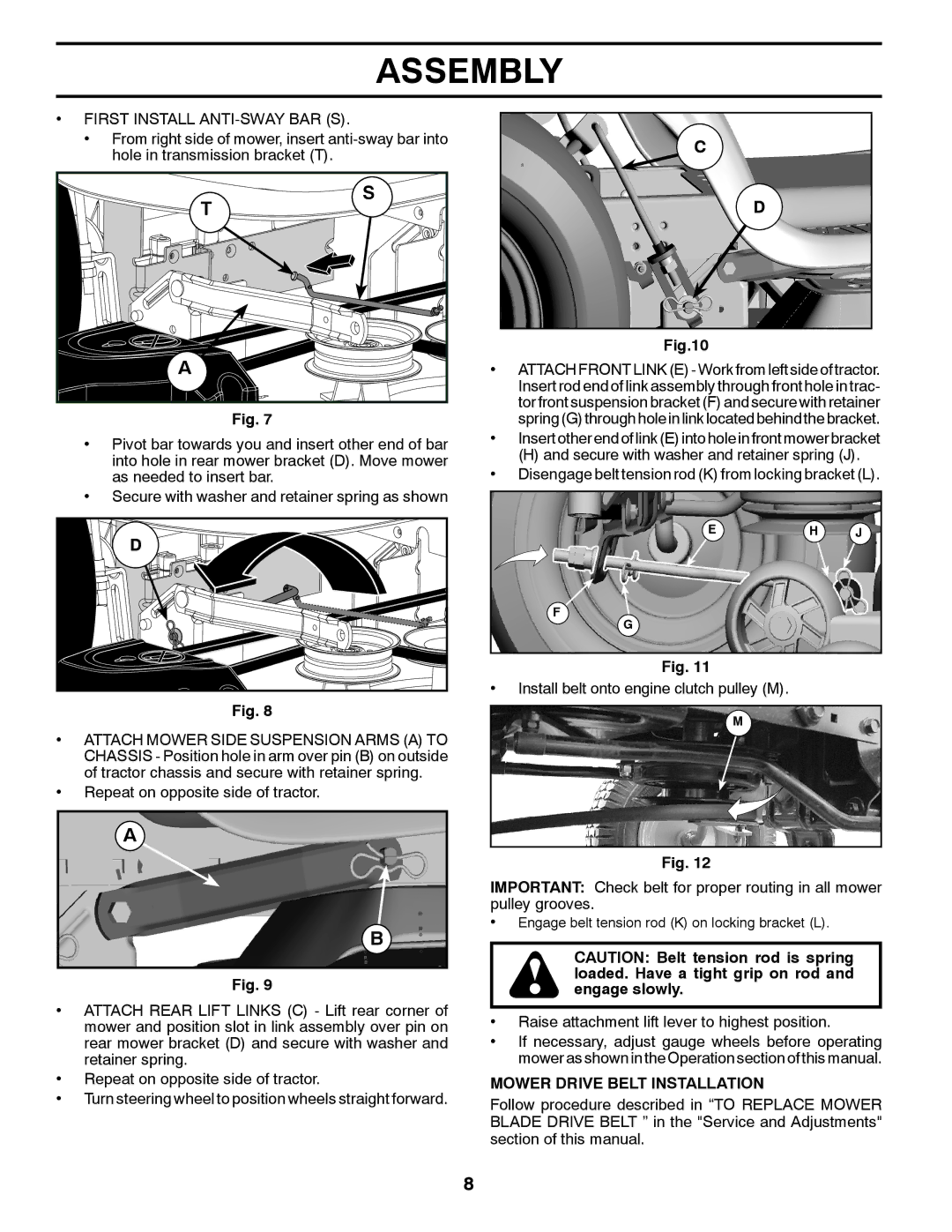
•FIRST INSTALL ANTI-SWAY BAR (S).
•From right side of mower, insert
| T | S |
|
| |
A |
| • |
|
| Fig. 7 |
• Pivot bar towards you and insert other end of bar | • |
| |
into hole in rear mower bracket (D). Move mower | • |
as needed to insert bar. |
•Secure with washer and retainer spring as shown
D ![]()
•
C
D
Fig.10
ATTACH FRONT LINK (E) - Work from left side of tractor. Insert rod end of link assembly through front hole in trac- tor front suspension bracket (F) and secure with retainer spring(G) throughhole inlinklocatedbehind the bracket.
Insert other end of link (E) into hole in front mower bracket
(H)and secure with washer and retainer spring (J). Disengage belt tension rod (K) from locking bracket (L).
EH J
F![]()
G
Fig. 11
Install belt onto engine clutch pulley (M).
Fig. 8
•ATTACH MOWER SIDE SUSPENSION ARMS (A) TO CHASSIS - Position hole in arm over pin (B) on outside of tractor chassis and secure with retainer spring.
•Repeat on opposite side of tractor.
A
B
Fig. 9
•ATTACH REAR LIFT LINKS (C) - Lift rear corner of mower and position slot in link assembly over pin on rear mower bracket (D) and secure with washer and retainer spring.
•Repeat on opposite side of tractor.
•Turn steering wheel to position wheels straight forward.
M
Fig. 12
IMPORTANT: Check belt for proper routing in all mower pulley grooves.
•Engage belt tension rod (K) on locking bracket (L).
CAUTION: Belt tension rod is spring loaded. Have a tight grip on rod and engage slowly.
•Raise attachment lift lever to highest position.
•If necessary, adjust gauge wheels before operating mower as shown in the Operation section of this manual.
MOWER DRIVE BELT INSTALLATION
Follow procedure described in “TO REPLACE MOWER BLADE DRIVE BELT ” in the "Service and Adjustments" section of this manual.
8