PORTABILITY KIT INSTALLATION
TOOLS REQUIRED: 7/16”, 1/2”, 9/16”, and 5/8" sockets and ratchets, block(s) of wood (minimum of 6” tall).
Refer to the parts list on pages 8 and 9.
WHEEL INSTALLATION
1.Block up end of generator opposite the fuel tank cap to install wheel kit.
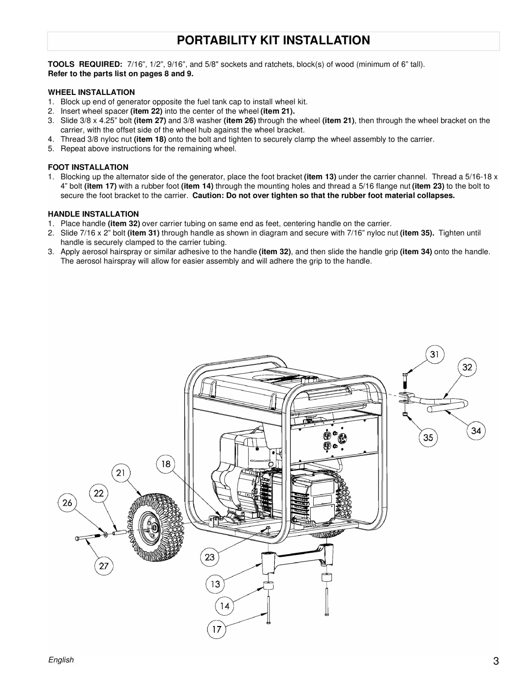
2.Insert wheel spacer (item 22) into the center of the wheel (item 21).
3.Slide 3/8 x 4.25” bolt (item 27) and 3/8 washer (item 26) through the wheel (item 21), then through the wheel bracket on the carrier, with the offset side of the wheel hub against the wheel bracket.
4.Thread 3/8 nyloc nut (item 18) onto the bolt and tighten to securely clamp the wheel assembly to the carrier.
5.Repeat above instructions for the remaining wheel.
FOOT INSTALLATION
1.Blocking up the alternator side of the generator, place the foot bracket (item 13) under the carrier channel. Thread a
HANDLE INSTALLATION
1.Place handle (item 32) over carrier tubing on same end as feet, centering handle on the carrier.
2.Slide 7/16 x 2” bolt (item 31) through handle as shown in diagram and secure with 7/16” nyloc nut (item 35). Tighten until handle is securely clamped to the carrier tubing.
3.Apply aerosol hairspray or similar adhesive to the handle (item 32), and then slide the handle grip (item 34) onto the handle. The aerosol hairspray will allow for easier assembly and will adhere the grip to the handle.
English |
| 3 |
| ||
|
|
|